20.2.14: JFET-Verstärkerstufe berechnen
Wolfgang Schmidt schrieb: Wie berechne ich in folgender Schaltung aus Ihrem Buch „Grundwissen Elektronik“ die Source Wechselspannung am Source-Widerstand in Abhängigkeit von der Eingangsspannung, der Frequenz und der Kondensatorkapazität?
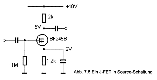
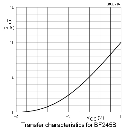
Erstmal fällt mir da gleich ein Fehler auf. Entweder die 2 V an Source oder die 5 V am Drain können nicht stimmen. Durch beide Widerstände fließt der gleiche Strom. Wenn am 2-k-Widersatnd 5 V abfallen beträgt der Drainstrom 2,5 mA. Am Source-Widerstand fallen dann 2,5 mA * 1,2 k = 3 V ab, nicht 2 V. Welche Spannung sich tatsächlich einstellen wird hängt von den Daten des Transistors ab. Das Datenblatt zum JFET BF245B zeigt, dass man bei -2 V am Gate, bezogen auf Source, einen Drainstrom von 2,5 mA erwarten kann. Demnach müsste der Source-Widerstand auf 2 V / 2,5 mA = 0,8 kOhm festgelegt werden. 820 Ohm wäre passend. Jetzt kann ich den Fehler nachvollzeihen, damals habe ich anscheinend falsch rum geteilt, sehr peinlich. Also mit 820 Ohm würde der Rest stimmen.
Jetzt muss noch die untere Grenzfrequenz bestimmt werden. Den Source-Widerstand und den parallelen Kondensator kann man zusammen wie einen Hochpass berechnen. Dazu nehme ich inzwischen immer meinen Online-Rechner: OnlineRechner/Grenzfrequenz
Da ergibt sich z.B. dies: Mit 0,82 k und 1000 nF (= 1 µF) hat man eine untere Grenzfrequenz von 194 Hz, was gut zu Audio-Anwendungen passt. Außer wenn es um HiFi geht, dann wären 10 µF und 19,4 Hz besser. Weil der Eingangswiderstand der Schaltung mit 1 M sehr hoch ist reicht am Eingang ein Koppelkondensator von 10 nF für eine untere Grenzfrequenz von 15,9 Hz. Und der Ausgangs-Koppelkondensator richtet nach der Impedanz der nachfolgenden Stufe. Man könnte z.B. etwas mit 2 k anschließen, dann wäre ein Kondensator mit 4,7 µF angemessen und würde auf 16,9 Hz hinauslaufen.
Sourcewiderstand und Grenzfrequenz, von Harald Schetter
Die Berechnung der unteren Grenzfrequenz darf nicht allein mit dem offensichtlichen Widerstand an der Source erfolgen, es muss auch der im FET versteckte Sourcewiderstand berücksichtigt werden. Das ist der Kehrwert aus der Steilheit, die hier auch aus der Steuerkurve entnommen werden kann. Im vorliegenden Fall etwa 2,5 mA/V entsprechend 400 Ohm. Dieser nichtlineare, aussteuerungsabhängige Widerstand parallel zu den korrigierten 820 Ohm erfordert also mindestens die dreifache Kapazität. Und weil der versteckte Widerstand sich dynamisch ändert (siehe Steuerkurve), werden in der Verstärkerstufe nicht nur Amplitudenverzerrungen erzeugt sondern in Verbindung mit dem Kondensator auch aussteuerungsabhängige Phasenfehler. Letzteres ist mit ein Grund, dass man Abblockkondensatoren nicht zur Beeinflussung des Frequenzgangs verwenden soll.
Bei bipolaren Transistoren ist die Steuerkurve bekanntermaßen viel steiler und der dort versteckte Emitterwiderstand noch niederohmiger. Um zuverlässige Ergebnisse zu erzielen, wird (nicht nur dort) in Reihe zu den Abblockkondensatoren immer ein niederohmiger Widerstand geschaltet, der die Berechnung vereinfacht und im Endeffekt Verzerrungen vermindert.
Wolfgang Schmidt schrieb: Wie berechne ich in folgender Schaltung aus Ihrem Buch „Grundwissen Elektronik“ die Source Wechselspannung am Source-Widerstand in Abhängigkeit von der Eingangsspannung, der Frequenz und der Kondensatorkapazität?

Erstmal fällt mir da gleich ein Fehler auf. Entweder die 2 V an Source oder die 5 V am Drain können nicht stimmen. Durch beide Widerstände fließt der gleiche Strom. Wenn am 2-k-Widersatnd 5 V abfallen beträgt der Drainstrom 2,5 mA. Am Source-Widerstand fallen dann 2,5 mA * 1,2 k = 3 V ab, nicht 2 V. Welche Spannung sich tatsächlich einstellen wird hängt von den Daten des Transistors ab. Das Datenblatt zum JFET BF245B zeigt, dass man bei -2 V am Gate, bezogen auf Source, einen Drainstrom von 2,5 mA erwarten kann. Demnach müsste der Source-Widerstand auf 2 V / 2,5 mA = 0,8 kOhm festgelegt werden. 820 Ohm wäre passend. Jetzt kann ich den Fehler nachvollzeihen, damals habe ich anscheinend falsch rum geteilt, sehr peinlich. Also mit 820 Ohm würde der Rest stimmen.

Jetzt muss noch die untere Grenzfrequenz bestimmt werden. Den Source-Widerstand und den parallelen Kondensator kann man zusammen wie einen Hochpass berechnen. Dazu nehme ich inzwischen immer meinen Online-Rechner: OnlineRechner/Grenzfrequenz
Da ergibt sich z.B. dies: Mit 0,82 k und 1000 nF (= 1 µF) hat man eine untere Grenzfrequenz von 194 Hz, was gut zu Audio-Anwendungen passt. Außer wenn es um HiFi geht, dann wären 10 µF und 19,4 Hz besser. Weil der Eingangswiderstand der Schaltung mit 1 M sehr hoch ist reicht am Eingang ein Koppelkondensator von 10 nF für eine untere Grenzfrequenz von 15,9 Hz. Und der Ausgangs-Koppelkondensator richtet nach der Impedanz der nachfolgenden Stufe. Man könnte z.B. etwas mit 2 k anschließen, dann wäre ein Kondensator mit 4,7 µF angemessen und würde auf 16,9 Hz hinauslaufen.
Sourcewiderstand und Grenzfrequenz, von Harald Schetter
Die Berechnung der unteren Grenzfrequenz darf nicht allein mit dem offensichtlichen Widerstand an der Source erfolgen, es muss auch der im FET versteckte Sourcewiderstand berücksichtigt werden. Das ist der Kehrwert aus der Steilheit, die hier auch aus der Steuerkurve entnommen werden kann. Im vorliegenden Fall etwa 2,5 mA/V entsprechend 400 Ohm. Dieser nichtlineare, aussteuerungsabhängige Widerstand parallel zu den korrigierten 820 Ohm erfordert also mindestens die dreifache Kapazität. Und weil der versteckte Widerstand sich dynamisch ändert (siehe Steuerkurve), werden in der Verstärkerstufe nicht nur Amplitudenverzerrungen erzeugt sondern in Verbindung mit dem Kondensator auch aussteuerungsabhängige Phasenfehler. Letzteres ist mit ein Grund, dass man Abblockkondensatoren nicht zur Beeinflussung des Frequenzgangs verwenden soll.
Bei bipolaren Transistoren ist die Steuerkurve bekanntermaßen viel steiler und der dort versteckte Emitterwiderstand noch niederohmiger. Um zuverlässige Ergebnisse zu erzielen, wird (nicht nur dort) in Reihe zu den Abblockkondensatoren immer ein niederohmiger Widerstand geschaltet, der die Berechnung vereinfacht und im Endeffekt Verzerrungen vermindert.
10.2.14: Schrittmotor am ULN2003 und Tiny13, von Heinz D.
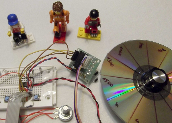
Modellbahn-Drehscheibe, oder Schrittmotor-Platine tötet drei T13 innerhalb einer Stunde!
Eine
Modellbahn-Drehscheibe sollte so angetrieben werden, das die Position
mit einem Poti eingestellt werden kann. Da fiel unser Auge auf einen
Getriebeschrittmotor mit Platine. Die Platine ist mit einem ULN2003
bestückt. Obwohl das Datenblatt Schutzdioden gegen Pin9 an +5V
darstellt, scheint die Induktionsspannung einen Weg zu den Ports zu
finden. Im einfachsten Fall hängt sich der T13 auf und lässt sich mit
Reset zum arbeiten bewegen. Während der Programmentwicklung schiebt man
einen toten T13 auf Verdrahtungsfehler oder eigene Dummheit. Nach dem
zweiten wird man vorsichtig. Beim dritten war das Programm schon fast
fehlerfrei. Sein Tod konnte kein Versehen mehr sein. Also vier Schottky-Dioden 1N5817
an die Motorspulen nach +5V und ein 47uF an +5V-Gnd. Und siehe da, Nr.4
lebt und erfreut sich bester Gesundheit.
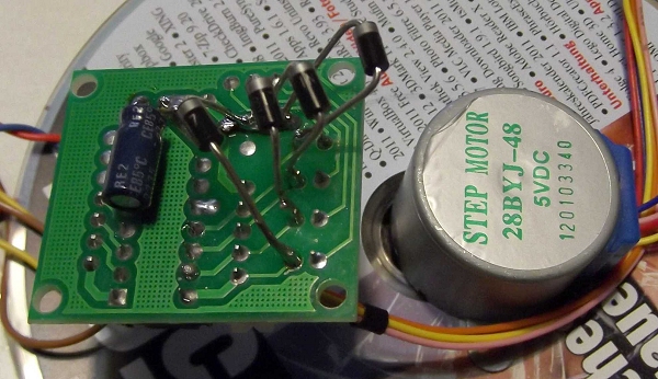
Fazit?
Sind die Dioden etwas schlapp? oder zu langsam? oder zu hochohmig? Ich weiß es nicht. Ggf. hätte der 47uF gereicht um die Induktionsspitzen zu blocken, aber ich wollte nicht noch einen T13 riskieren. Vielleicht hilft es anderen Lesern.
Das Programm ist primitiv und nur ein Gerüst und kann leicht auf andere AVR geändert werden. Der Motor läuft der Poti-Stellung (AD-Wert=0-270°) hinterher und benötigt 2048 Schritte für 360°.
Download: Schrittmotor-bas-hex.zip

Modellbahn-Drehscheibe, oder Schrittmotor-Platine tötet drei T13 innerhalb einer Stunde!

Fazit?
Sind die Dioden etwas schlapp? oder zu langsam? oder zu hochohmig? Ich weiß es nicht. Ggf. hätte der 47uF gereicht um die Induktionsspitzen zu blocken, aber ich wollte nicht noch einen T13 riskieren. Vielleicht hilft es anderen Lesern.
Das Programm ist primitiv und nur ein Gerüst und kann leicht auf andere AVR geändert werden. Der Motor läuft der Poti-Stellung (AD-Wert=0-270°) hinterher und benötigt 2048 Schritte für 360°.
Download: Schrittmotor-bas-hex.zip
5.2.14: Long Tailed Pair, Hinweise von Fabian Amann
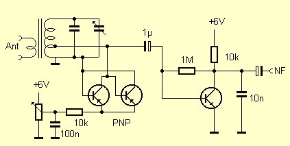
Ich mache mir nun schon seit Wochen Gedanken über einen Schaltungsblock in einer in Ihrem Radio-Baubuch beschriebenen Schaltung. Konkret geht es um Abschnitt 4.4: Separate Rückkopplung auf Seite 58 Bild 4.8 bzw. S. 60 Bild 4.10.
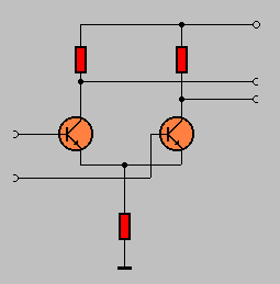
Hier wird der Verstärker für die Rückkopplung mit zwei PNP-Transistoren realisiert. Sie benennen diese Schaltung in Ihrem Buch als "Differenzverstärkerstufe". Wenn ich mich an meine Diplomarbeit zurückerinnere und an die Lehrbücher von Horowitz und Hill, beschreiben diesen einen Differenzverstärker unter "Long Tailed Pair" bzw. in der "hervorragenden" Übersetzung als "Paar mit langem Schwanz" (sic!).
Technisch sind hier jedoch die Anschlüsse anders verdrahtet. Als Eingänge dienen die Basisanschlüsse. In Ihrer Schaltung kann ich dies auch erkennen, nur dass der nicht verwendete Eingang eben nicht auf GND oder U_B liegt. Auch die Kollektoren sind in Horowitz/Hill gemeinsam verschaltet, auch das finde ich in Ihrer Schaltung nicht. Können Sie mich über die Funktionsweise dieser konkreten Schaltung aufklären? Hat sie einen besonderen Namen? Was waren die Gedanken dahinter, es nicht "klassisch" als "Long Tail Pair" aufzubauen?
Versuch einer Antwort:
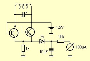
Ich bin gedanklich von einem einfachen Differenzverstärker ausgegangen. Wenn man sich den Schwingkreis in der Schaltung oben mit einer Mittelanzapfung vorstellen würde, könnte dieser Verstärker ganz symmetrisch angeschlossen werden. Aber es funktioniert eben auch unsymmetrisch.
Genau diese Schaltung wird auch als Long Tail Pair bezeichnet. Oft wird sie zur Phasendrehung eingesetzt. Auch wenn man nur einen der beiden Eingänge ansteuert, kommen beide Phasen hinten heraus.
http://www.radio-electronics.com/info/circuits/transistor/long-tailed-pair.php
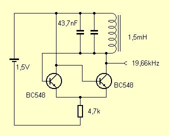
Es gibt noch eine andere Betrachtungsweise: Der linke Transistor arbeitet als Emitterfolger. Am Ausgang (am Emitter) ist dann der zweite Transistor in Basisschaltung angeschlossen. Der linke Transistor bringt nur Stromverstärkung, der rechte nur Spannungsverstärkung. Beide erzeugen keine Phasendrehung, deshalb ist die Rückkopplungsbedingung erfüllt.
Die Schaltung habe ich mal vor vielen Jahren in einer Amateurfunkanwendung entdeckt und fand sie immer schon sehr praktisch. Den offiziellen Namen kenne ich aber leider nicht. Sie zeichnet sich durch hohe Verstärkung und Schwingfreudigkeit aus. Dieser Oszillator schwingt immer, auch wenn der Kreis starke Dämpfung aufweist oder wenn man ein sehr ungünstiges L/C-Verhältnis verwendet. Daher kann man damit auch große Frequenzbereiche mit nur einer Spule überstreichen. Einen Nachteil gibt es aber auch: Die sehr direkte Kopplung zwischen Schwingkreis und Transistoren führt dazu, dass sich die Transistorkapazitäten stark auswirken und dass die Stabilität bei Schwankungen der Versorgungsspannung bescheiden ist. Weitere Anwendungen dieses Oszillators:
Einfaches Dipmeter: b-kainka.de/bastel53.htm
Nachtrag von Rudolf Drabek, aeerde.wordpress.com
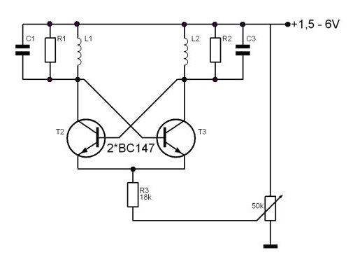
Mein ELO-Beitrag: Oszillator schwingt auf zwei Frequenzen ist selbsterklärend.
Üblicherweise besteht das LTP aus 3 Transistoren. Nämlich einem Transistor mit dem Kollektor an den beiden Emittern. So kann man gut den Arbeitspunkt für das LTP einstellen. Aber auch den Strom modulieren mit einem eingeprägten Signal.
Übrigens bezeichnet man zwei LTP'S geeignet geschaltet als Gilbert Cell. Der beste lineare Modulator bis über 100% den es gibt. Je nach Arbeitspunkt auch ein Doppelseitenbandmodulator mit unterdrücktem Träger. Wird oft auch zur SSB Signalaufbereitung benützt.
Emittergekoppelter Oszillator, eine Namensklärung von Gerhard Kircher
Der mit dem Differenzverstärker aufgebaute Oszillator wird als "Emittergekoppelter Oszillator" bezeichnet. Tietze/Schenk sagt dazu: "Ein Oszillator lässt sich auf einfache Weise [...] mit einem Differenzverstärker realisieren. Da das Basispotential von T1 mit dem Kollektorpotential von T2 in Phase ist, kann man die Mitkopplung durch direkte Verbindung erzeugen. Die Schleifenverstärkung [...] lässt sich durch Änderung des Emitterstromes in weiten Grenzen einstellen."
(Halbleiter-Schaltungstechnik/U.Tietze, Ch.Schenk/Springer-Verlag, z.B. 7. Auflage S.446 oder 12. Auflage S.878)
Danke für diese Namensklärung! Diese Bezeichnung macht Sinn. Es freut mich auch, dass Tietze/Schenk ebenfalls dahinter einen Differenzverstärker sieht. Das Buch steht bei mir im Regal, aber ich war gar nicht auf die Idee gekommen, darin zu suchen. Und wenn man im Internet sucht, muss man ja erstmal den Namen wissen. Im Netz findet man den Emittergekoppelten Oszillator u.a. in einem Patent von 1980, aber ich bin davon überzeugt, dass Dietrich Drahtlos diese Schaltung schon lange vorher entwickelt hat. Eine andere Bezeichnung ist offenbar "Differenzverstärker-Oszillator": http://de.wikipedia.org/wiki/Differenzverst%C3%A4rker-Oszillator
Separated Q-Multiplying, by D.A.W. Mast
At Notizen/LTspice/Oszillatori.html and here you write about the emitter coupled oscillator which is also used in the regenerative shortwave receiver at www.b-kainka.de/bastel3.htm Advantage of that circuit is that detection and Q-Multiplying has been separated, each stage has been optimally designed for its task, a sensitive detection and a smooth and backlash-free regeneration control. It is always a good practice to separate detection and Q-Multiplying in two distinct stages in solid-state regenerative receivers.
See also www.b-kainka.de/Weblog/HF/UKWaudion.html
This oscillator topology is often used in Local Oscillators in single-chip AM superhet receivers, very easy for using it in multi-band shortwave receivers, because band-switching is much easier than in superhets in which tickler coils or coil taps have been used.
And another advantage of separating detecting and Q-Multiplying is that you will not suffer from issues like squegging and motorboating. which is called fringe howl. At www.mikrocontroller.net/topic/299578 "unerwünschten Schwingungen im Audio-bereich" I am talking about that problem in regenerative receivers in which detection and Q-Multiplying are combined in one single stage. On www.b-kainka.de/bastel86.htm you mention the hand-effects while tuning the Retro Radio on the 80 m band. To avoid hand-effects you should use a grounded base RF-preamp stage in any regenerative receiver. Like the RF-preamp in the Beast-receiver at www.elektronik-labor.de/HF/BEAST.html.
It is also possible to build a medium wave regenerative receiver which can be preceded by a shortwave converter stage like the Kurzwellen Konverter at www.b-kainka.de/bastel86.htm. In this case the regenerative receiver forms the IF-stage. This kind of a superhet with a regenerative IF-stage is called a SuperGainer or a Regenerodyne.
At www.elo-web.de/bauprojekte/feierabendprojekte/ukw-audion-mit-variometer and www.b-kainka.de/Weblog/logbuch3.html you are talking about regenerative receivers for the FM-Broadcastband. These receivers are synchronous oscillators which are frequency-locked onto the frequency deviations of the incoming FM RF-signal. These deviations are converted to the AF signal by the synchronous oscillator. At www.electroschematics.com/4663/small-fm-receiver/ there is an FM-receiver with also an emitter-coupled oscillator which is locked onto the frequency deviations of the incoming FM RF-signal. FM-detection by a synchronous oscillator gives a much better AF quality than using a superregenerative receiver.
At www.theradioboard.com and groups.yahoo.com/groups/regenrx you can discuss about regenerative and superhet receivers.
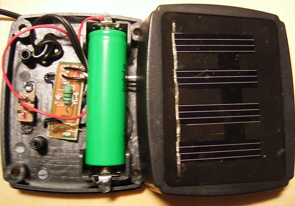
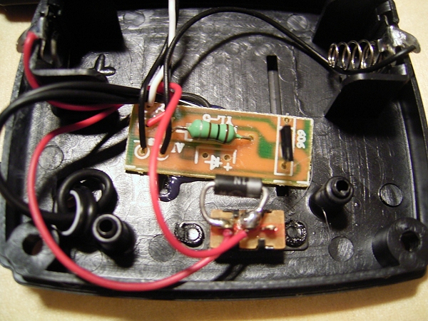
Im letzten Sommer war eine Solarleuchte mit einer Solarzelle und vier abgesetzten Lampen im Betrieb. Die kleine Energiestation mit Akku, Solarzelle und Spannungswandler hat auch einen Schalter. Manchmal bei schlechtem Wetter wurde die Lampe ausgeschaltet. Der Gedanke war, dann kann der Akku ein paar Tage lang laden, und wird's schon wieder gehen. Das hat aber nie richtig funktioniert. Schon da hatte ich den bösen Verdacht einer Fehlkonstruktion. Kann das wirklich sein, dass im abgeschalteten Zustand auch der Akku nicht mehr geladen wird? Jetzt im Winter kam mir die Lampe wieder unter die Finger. Aufgeschraubt und nachgesehen: Tatsächlich, da wird einfach nur der Akku abgeschaltet. Das muss anders werden. Deshalb habe ich jetzt eine Schottkydiode über den Schalter gelegt. Damit wird immer geladen, wenn die Sonne scheint. Auch dann, wenn der Schalter aus ist.
