Stepper Motor Controller mit ATtiny2313
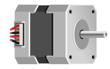
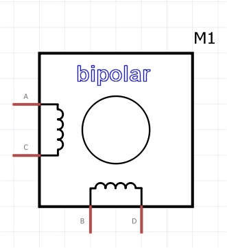
Ein altes Floppy Laufwerk enthält viele nützliche Bauteile, unter anderem ein paar DC Motoren und einen Schrittmotor. Der müsste sich irgendwie bewegen lassen. Das ist dann doch etwas komplizierter, denn das ist ein bipolarer Schrittmotor mit vier Anschlüssen und zwei Spulen. Insofern braucht man eine H Brücke, um den Strom durch die Spulen passend umzupolen. Ein L293 enthält 2 H Brücken, der lässt sich bis 1 A Spulenstrom als Treiber einsetzen.
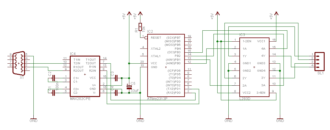
Die Ansteuerung des L293 übernimmt ein ATtiny2313, die Sequenz dafür ist in einer Tabelle abgelegt, die zyklisch durchlaufen wird. Die Signale sind an PB0 bis PB3. Das Ganze ist in Assembler, so ist es schnell. Der ATtiny2313 wird über die serielle Schnittstelle programmiert, als Pegelwandler für RS232 dient ein MAX202. Folgende Kommandos sind möglich:
+xx cw xx steps, xx is binary -xx ccw xx steps sxx speed xx, xx is binary x stop e set output PD6 (can connect to L293 enable) d reset output PD6 1 single step
Mit +xx steps bestimmt man die Anzahl der Schritte, z.B. +00000011 11101000 (+ und 2 bytes) dreht der Motor 1000 Schritte im Uhrzeigersinn. Die Umrechnung von dezimal 1000 in eine Binärzahl macht der Laptop, das ist einfacher als im controller. Das Kommando s und 2 bytes bestimmt die Drehgeschindigkeit des Motors. Diese 2 bytes setzen OCR1A direkt. Die Frequenz ist f = fclock / ( OCR1A + 1 ), je grösser der Wert desto langsamer dreht der Motor. Die Frequenz sollte nicht zu hoch sein, sonst brummt es aber dreht nicht.
Schaltbild des Schrittmotor Controllers
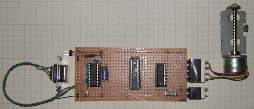
Die Platine, rechts der Anschluss für den Schrittmotor und die Spannungsversorgung für den Motor
Siche auch: Mini-Schrittmotor-Innleben
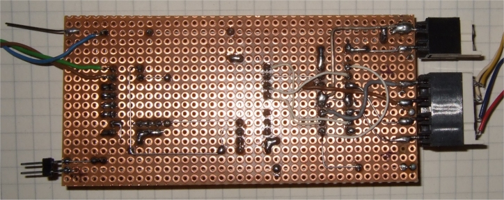
Die Platine von unten, wilde Verdrahtung beim L293
Dieser Schrittmotor hat 40 Schritte für eine Umdrehung, das sind 9 Grad pro Schritt, nicht besonders beeindruckend, und er läuft schon im Halbschrittbetrieb. Damit lässt sich auch ein anderer Motor ansteuern, oder man kann einen 6-Draht Motor nehmen, dann muss man die Tabelle ändern und braucht noch eine weitere H Brücke. Es war ein Funktionsmodell um zu sehen, ob der alte Floppymotor zu neuem Leben erwacht. Er lebt, bescheiden wie vorher.
datasheet ATtiny2313, Atmel.com
datasheet MAX202, Maxim
datasheet L293, STMicroelectronics
Download: stepper2.zip;***************************************************************************
; medium speed bipolar step motor controller
;
; floppy drive step motor has 40 steps per revolution
;
; Target ATtinz2313, 4 MHz internal osc
; GS updated 01-2014 Stepmotor ctrl
;
; all controlled by RS232 commands:
; +xx: cw xx steps, xx is binary
; -xx: ccw xx steps
; sxx: speed xx, xx is binary
; x: stop
; e: set output PD6 (can connect to L293 enable)
; d: reset output PD6
; 1: single step
;
; This program is free software; you can redistribute it and/or
; modify it under the terms of the GNU General Public License.
; This program is distributed in the hope that it will be useful,
; but WITHOUT ANY WARRANTY;
;
;
;;***************************************************************************
; ATiny2313 PDIP
;
; (RESET/dW) PA2 1 20 VCC
; (RXD) PD0 2 19 PB7 (UCSK/SCK/PCINT7)
; (TXD) PD1 3 18 PB6 (MISO/DO/PCINT6)
; (XTAL2) PA1 4 17 PB5 (MOSI/DI/SDA/PCINT5)
; (XTAL1) PA0 5 16 PB4 (OC1B/PCINT4)
; (CKOUT/XCK/INT0)PD2 6 15 PB3 (OC1A/PCINT3)
; (INT1) PD3 7 14 PB2 (OC0A/PCINT2)
; (T0) PD4 8 13 PB1 (AIN1/PCINT1)
; (OC0B/T1) PD5 9 12 PB0 (AIN0/PCINT0)
; GND 10 11 PD6 (ICP)
;***************************************************************************
.DEVICE ATtiny2313 ;for gavrasm 33
;*************** Define global registers ********************************
.def sr = r15
.def temp = R16
.def direction = r17
.def index = r18
.def next_step = r19
.def stepsL = r20
.def stepsH = r21
.def XL = r26 ; X stepcounter
.def XH = r27
.def ZL = r30 ; Z steptable
.def ZH = r31
;*************** Define constants ********************************
.equ c_value = 8000-1 ; Compare value for compare interrupt
; 8000 cycles @ 4Mhz = 2ms
.equ clock = 4000000
.equ baudrate = 19200
.equ baudval = clock/(16*baudrate)-1
;************************************************************************=
;*
;* PROGRAM START - EXECUTION STARTS HERE
;*
;************************************************************************=
.cseg
.org 0
rjmp RESET
reti ; ExtInt0
reti ; INT1
reti
rjmp T1OC1A ; Initialize T1 Compare Match A interrupt vector
.org 7
rjmp RX_COMPLETE_INT
;************************************************************************=
;step: .db 0x19,0x2C,0x36,0x03 Step motor lookup table
; bipolar stepper motor:
Dummy:
.db 0, 0,
HalfstepCW:
;.db b00000101, b00000001, b00001001, b00001000, b00001010, b00000010, b00000110, b00000100
.db 0x05, 0x01, 0x09, 0x08, 0x0A, 0x02, 0x06, 0x04
.db 0, 0
;HalfstepCCW:
;.db b00000100, b00000110, b00000010, b00001010, b00001000, b00001001, b00000001, b00000101
;************************************************************************=
;*
;* OC1A - Timer1 Compare Match A interrupt routine
;*
;************************************************************************=
T1OC1A: in sr, SREG ;
cp XL,stepsL ; target steps reached?
cpc XH,stepsH ; if same or higher
brsh oc1a_ex ; just return
inc next_step ; else time to step
adiw XL,1 ; inc stepscounter
oc1a_ex: out SREG,sr
reti
;****************************************************************************
; reset
;****************************************************************************
reset: ;Intialize stackpointer
ldi temp, RAMEND
out SPL, temp
ldi temp,low(baudval) ; UBRRL set uart speed to 19.6 kbps
out UBRRL,temp
ldi temp,high(baudval)
out UBRRH,temp
; UCSRB: RXCIE TXCIE UDRIE RXEN TXEN UCSZ2 RXB8 TXB8
ldi temp,0x98 ;UCSRB=UCR enable RXint and enable tx/rx
out UCSRB,temp ; 98 = 10011000
ldi temp,0x0F ;Set PORTB as output
out DDRB,temp
ldi temp,0x00
out PORTB,temp ;Write initial value to PORTB
sbi DDRD, PIND6 ; enable output
sbi PORTD, PIND6
ldi temp,high(c_value) ;Load compare high value
out OCR1AH,temp
ldi temp,low(c_value) ;Load compare low value
out OCR1AL,temp
ldi temp,0x00
out TCNT1H,temp ;Clear timer high byte
out TCNT1L,temp ;Clear timer low byte
out TCCR1A,temp ;Clear timer control reg A
ldi temp,0x40 ;TOV1 OCF1A OCF1B – ICF1 OCF0B TOV0 OCF0A: TIFR
out TIFR,temp ;Clear pending timer interrupt
out TIMSK,temp ;Enable Timer compare interrupt
;TOIE1 OCIE1A OCIE1B – ICIE1 OCIE0B TOIE0 OCIE0A: TIMSK
ldi ZH,high(HalfstepCW*2) ;Initialize Z pointer to step motor table in flash
ldi ZL,low(HalfstepCW*2)
clr index
clr next_step
ldi direction, 1 ;0=ccw 1=cw
clr stepsL ;steps target
clr stepsH
clr XL
clr XH ;steps counter
ldi temp,0b00001001 ;0x9
out TCCR1B,temp ;Clear timer on compare match,CK/1
sei ;Enble global interrupt
;****************************************************************************
loop:
tst next_step ;if 1, time to step
breq loop
clr next_step ;ready for next
cpi direction, 0 ;0=ccw 1=cw
breq m_ccw
;cw
inc ZL
lpm temp, Z ;Move value
tst temp ;upper end of table?
breq m_icw
out PORTB,temp ;Output lower nibble to step motor
rjmp loop
m_icw: ldi ZL,low(HalfstepCW*2)
lpm temp, Z ;Move value
out PORTB,temp ;Output lower nibble to step motor
rjmp loop
m_ccw:
dec ZL
lpm temp, Z ;Move value
tst temp ;lower end of table?
breq m_iccw
out PORTB,temp ;Output lower nibble to step motor
rjmp loop
m_iccw: ldi ZL,low(HalfstepCW*2)
subi ZL, -7 ;point to end of table
lpm temp, Z ;get value
out PORTB,temp ;Output lower nibble to step motor
rjmp loop ;again
;**********************************************************************
; communication functionality
;**********************************************************************
; send char in temp
;
send_char:
push temp ; save temp
send_c2:
in temp,UCSRA ; wait for the transmitter to be ready
sbrs temp,5 ; ready ?
rjmp send_c2 ; no, wait some more
pop temp ; restore temp
out UDR,temp ; send char
ret ; ans return
;
; send the current steps to the PC
; as a 5 byte sequence :
; 'OK' followed by a 16 bit steps value
;
;
send_data:
push temp ; save temp
ldi temp,'O' ; flag
rcall send_char
ldi temp,'K' ; flag
rcall send_char
mov temp,XH
rcall send_char ; high steps
mov temp,XL
rcall send_char ; low steps
ldi temp,0x0a
rcall send_char ; terminator
pop temp
ret
;
; read in 2 characters from the serial link
;
read_2:
rcall get_char ; read bits 15..8
mov stepsH,temp
rcall get_char ; read bits 7..0
mov stepsL,temp
ret
;
; get char in temp
;
get_char: ; UCSRA: RXC TXC UDRE FE DOR UPE U2X MPCM
in temp,UCSRA ; UCSRA =USR wait for a byte to be ready
sbrs temp,7 ; ready ?
rjmp get_char ; no, wait some more
in temp,UDR ; get the byte
ret ; and return
stop_timer: ldi temp,0b00000000 ;stop timer
out TCCR1B,temp ;Clear timer
out TCNT1H,temp ;Clear timer high byte
out TCNT1L,temp ;Clear timer low byte
ret
;
; Interrupt routine for incoming bytes on the RS232 link
;
RX_COMPLETE_INT:
in sr, SREG
push temp
in temp,UDR
cpi temp,'+' ; cw + steps 2 bytes
brne tx_2
rcall stop_timer
rcall read_2
ldi direction, 1 ; 0=ccw 1=cw
clr XL ; clear step counter X
clr XH
ldi temp,0b00001001 ;0x9, restart
out TCCR1B,temp ;Clear timer on compare match,CK/1
rjmp tx_exit
tx_2:
cpi temp,'-' ; ccw
brne tx_3
rcall stop_timer
rcall read_2
ldi direction, 0 ; 0=ccw 1=cw
clr XL ; clear step counter X
clr XH
ldi temp,0b00001001 ;0x9, restart
out TCCR1B,temp ;Clear timer on compare match,CK/1
rjmp tx_exit
tx_3:
cpi temp,'s' ; speed + 2 bytes
brne tx_4
rcall stop_timer
rcall get_char
out OCR1AH,temp
rcall get_char
out OCR1AL,temp
ldi temp,0b00001001 ;0x9, restart
out TCCR1B,temp ;Clear timer on compare match,CK/1
rjmp tx_exit
tx_4:
cpi temp,'1' ;
brne tx_5
inc next_step ; 1 time to step
rjmp tx_exit
tx_5:
cpi temp,'x' ; stop
brne tx_6
rcall stop_timer
rjmp tx_exit
tx_6:
cpi temp,'e' ;
brne tx_7
sbi PORTD, PIND6 ; set output
rjmp tx_exit
tx_7:
cpi temp,'d' ;
brne tx_13
cbi PORTD, PIND6 ; reset output
rjmp tx_exit
; unknown command, just ignore it
tx_13:
; always reply with the current steps
tx_exit:
rcall send_data
pop temp
out SREG, sr
reti