
Timer with ATtiny2313
Compared to the simple timer with Attiny15 this timer is more accurate with a quartz to control the time. The time can be up to 99 hours and minutes and seconds can also be set. The range is from 1 second to 99h:59m:59s. I'm also using it to charge batteries or turn on a lamp for some time e.g. to make printed circuit boards.
There are 4 pushbuttons to control the operation.. The start pushbutton starts the time, turns on the relais and the timer will turn off the relais when the time is elapsed.
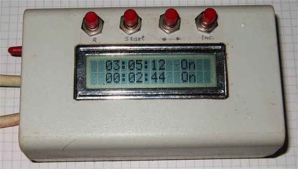
On the left is the reset button which will reset the timer and turn off the relais. The next is the start button, the display shows the programmed time in the upper line, 3 hours, 5 minutes and 12 seconds, and the lower line shows the time since the start button was pressed, 2 minutes and 44 seconds in this case and it shows that it is on. There is also a red led to show it's on.
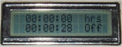
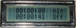
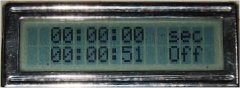
But first the time must be progammed. The next 2 buttons are used to do this. The ↔ button switches between programming hours, minutes and seconds and the inc button will increment the time. The display shows e.g. hrs on the upper right, then the inc button can increment the hours. The lower line shows the time since the unit was switched on and Off to indicate that the relais is off now.
It should be mentioned that the inc button can only increment the time, if you set the time higher than wanted then press reset and start again.
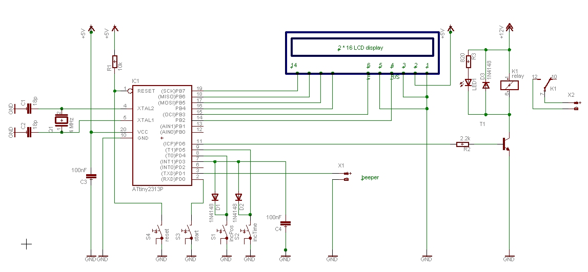
The circuit diagram, S4 is the reset button, and S3 is a pushbutton to start the timer. S1 and S2 will pull Int1 low through the diodes and in the interrupt routine the level on PD5 or PD4 determines which button was pressed., either the ↔ button or the inc button. On PD1 is a short signal when the time is elapsed, maybe could be connected to a buzzer, but I have not used it. PD6 is the timer output which is high when the timer is on, this turns on the transistor and the relais. Timing is controlled by the 4 MHz quartz crystal.
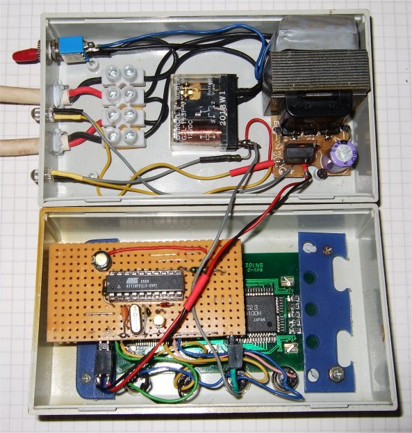
The timer in a box. Above is the power supply and the relais and
below the pcb with the Attiny2313 and the display board and the 4
pushbuttons.
The parts count is low and not expensive to make. Useful to have a
universal timer.
download LcdT04.asm
This program is distributed in the hope that it will be useful but WITHOUT ANY WARRANTY;
References
Atmel datasheet ATtiny2313, Atmel.com
Gerd's AVR assembler version 2.7:
http://www.avr-asm-tutorial.net/gavrasm/index_en.html
Eine Leserfrage: Gerne würde ich das Projekt nachbauen. Doch schon das Compilieren des Quellcodes klappt bei mir nicht.
Ich erhalte immer eine Fehlermeldung.
Anwort von Gerd Sinning:
Das
war ja interessant, ich wollte schon wissen was die Ursache war. Mit
gavrasm V2.5 compiliert LcdT04.asm fehlerfrei, aber ab V2.7 gibt es 2
Fehler, die das Z Register betreffen. Dann habe ich noch die neueste
V3.3 ausprobiert. Es geht erst, wenn man 2 Zeilen einfügt und Z
definiert
.def ZL = r30
.def ZH = r31
aber dann gehts.
Deshalb hier die neue Timer version 05 mit asm, hex und Listing: Timer05.zip
;***************************************************************************
; ATiny2313 Timer with LCD display GS 20.7.2009
; 	counts 1 second up to 99h:59m:59s
; 	uses 4 MHz quartz, program fuses accordingly
;   	working ok
;***************************************************************************
;
;  This program is free software; you can redistribute it and/or
;  modify it under the terms of the GNU General Public License.
;  This program is distributed in the hope that it will be useful,
;  but WITHOUT ANY WARRANTY;
;***************************************************************************
;
; * LCD-base routines for 4-Bit-interface of a 2-line LCD display
; Bits 7654=Data, Bit 2=RS, Bit3=E*   GS
; * Gerhard Schmidt, code basis
; ********************************************************************
;
; Hardware: LCD-Display on port B
; 	Pins  ATtiny2313:
;		R/S 	PortB 2
;		E 	PortB 3
;		DB4 	PortB 4
;		DB5 	PortB 5
;		DB6 	PortB 6
;		DB7 	PortB 7
;
;;***************************************************************************
;                 ATiny2313  PDIP
;
; (RESET/dW) 	  PA2 1   20 VCC
; (RXD) 	  PD0 2   19 PB7 (UCSK/SCK/PCINT7)
; (TXD) 	  PD1 3   18 PB6 (MISO/DO/PCINT6)
; (XTAL2) 	  PA1 4   17 PB5 (MOSI/DI/SDA/PCINT5)
; (XTAL1) 	  PA0 5   16 PB4 (OC1B/PCINT4)
; (CKOUT/XCK/INT0)PD2 6   15 PB3 (OC1A/PCINT3)
; (INT1) 	  PD3 7   14 PB2 (OC0A/PCINT2)
; (T0) 		  PD4 8   13 PB1 (AIN1/PCINT1)
; (OC0B/T1) 	  PD5 9   12 PB0 (AIN0/PCINT0)
;		  GND 10  11 PD6 (ICP)
;***************************************************************************
;
; PA2		Reset button on pin1
; PIND0		start button lo
; PIND1		short pulse out active high at end of timer
; PIND2		short pulse out active high when button pressed
; PD543	input , Pos and IncTime buttons diode wired or to ext int1 (GS)
; LedB1	= 1	PINB1 out heartbeat LedB1
; PIND6		Time out active high
;
.DEVICE ATtiny2313	;for gavrasm

.equ 		clock 		= 4000000

; Definition for the LCD-port
.equ 		cLcdWrite	= 0b11111111 	; Data direction write the LCD
.equ 		cLcdDummy	= 0b00111000 	; Dummy-Function-Word
.equ		line1		= 0b10000000
.equ		line2		= 0b11000000

; Definition for the LCD-port Hardware
.equ 		mLcdRs		= 0b00000100 	; RS-Bit Mask ; Port B2
.equ 		bLcdEn		= 3 		; Enable Bit    Port B3
.equ 		pLcdDdr		= DDRB		; LCD port
.equ 		pLcdPort	= PORTB		; PORTB

.equ 		c1s		= 200 		; Wait at start-up time (200 * 5 ms)
.equ 		c5ms		= clock/800 	; 5 ms Wait after each control word
.equ 		c50us		= clock/80000-4	; 50 us Wait after each char

; more Definitions

.equ	c_value			= 40000-1	; Compare value for output compare interrupt
						; 40000 cycles@4Mhz = 10000us = 10 ms
.equ	LedB1	= PINB1				; PINB1 out heartbeat LedB1
.equ	Apin	= PIND6				; timer output
.equ	ApinX	= PIND1

.equ	Tick	= PIND2

; Macro for Enable active time
;
; Version for 10 Mcs clock
;.MACRO enactive
;	nop
;	nop
;	nop
;	nop
;	nop
;.ENDMACRO
;
; Version für 4 Mcs clock
;
.MACRO enactive
	nop
	nop
.ENDMACRO
;

.def		Tsec	= r10
.def		Tmin	= r11
.def		Thrs	= r12
.def		digits	= r14
.def		sr	= r15

.def		temp	= r16
.def		LCDout	= r17
.def		lo_byte	= r18
.def		hi_byte	= r19
.def		flag	= r20
.def		second  = r23
.def		minute	= r24
.def		hour	= r25
.def		Tpos	= r26
.def		timer	= r27
.def		count	= r28

.cseg
.org 0
	rjmp	RESET
	reti			; INT0
	rjmp	ExtInt1
.org 4					;Initialize T1 Compare Match A interrupt vector
	rjmp	OC1A

;***************Timer1 Compare Match A interrupt ********************************
; 		10 ms


OC1A:		in	sr,sreg

		sbis	PINB,  LedB1		; heartbeat Led
		sbi	PORTB, LedB1		; set output PORTB, PINB1
		sbic	PINB,  LedB1	 	; skip if set
		cbi	PORTB, LedB1


		inc	count			; count up
		cpi 	count, 100		; 100 * 10 ms = 1 s
		brlo	OC1Ab
		clr	count

		inc	second
		cpi	second,60
		brne	OC1Ab
		clr	second

		inc	minute
		cpi	minute,60
		brne	OC1Ab
		clr	minute

		inc 	hour
		cpi	hour,100
		brne	OC1Ab
		clr	hour

OC1Ab:
		out	SREG,sr
		reti

;**********************************************************************
; External Interrupt1 on PIND3, button pressed
; change position PIND4 (IncPos) or PIND5 (IncTime)
;**********************************************************************
ExtInt1:
		in	sr, SREG
		sbi	PORTD, Tick
		rcall	LcdDelay5ms	; debounce
		rcall	LcdDelay5ms	; debounce
		sbis 	PIND, PIND5   	; check if button is high
		rcall	IncTime		; if low, IncTime Target time
		sbis 	PIND, PIND4   	; check if button is high
		rcall	IncPos		; if low, IncPos
		cbi	PORTD, Tick
		out	SREG, sr
		reti

;**********************************************************************

IncPos:
		inc 	Tpos
		andi	Tpos,0b00000011	; Max 0...3
		cpi	Tpos, 0
		breq	IncPhrs
		cpi	Tpos, 1
		breq	IncPmin
		cpi	Tpos, 2
		breq	IncPsec
		clr	Tpos

IncPhrs:
		ldi	LCDout,line1 + 12	; start at position 12
		rcall	Lcd4Ctrl
		ldi	ZH,high(2*T_hrs)	; setup Z pointer hi
		ldi	ZL,low(2*T_hrs)		; setup Z pointer lo
		rcall	Lcd4ZTxt1
		ret
IncPmin:
		ldi	LCDout,line1 + 12	; start at position 12
		rcall	Lcd4Ctrl
		ldi	ZH,high(2*T_min)	; setup Z pointer hi
		ldi	ZL,low(2*T_min)		; setup Z pointer lo
		rcall	Lcd4ZTxt1
		ret

IncPsec:
		ldi	LCDout,line1 + 12	; start at position 12
		rcall	Lcd4Ctrl
		ldi	ZH,high(2*T_sec)	; setup Z pointer hi
		ldi	ZL,low(2*T_sec)		; setup Z pointer lo
		rcall	Lcd4ZTxt1
		ret

;**********************************************************************

IncTime:
		cpi	Tpos, 0
		breq	IncThrs
		cpi	Tpos, 1
		breq	IncTmin
		cpi	Tpos, 2
		breq	IncTsec
IncThrs:	inc	Thrs
		mov	temp, Thrs
		cpi	temp,100
		brne	Incex
		clr	Thrs
		ret
IncTmin:	inc	TMin
		mov	temp, Tmin
		cpi	temp,60
		brne	Incex
		clr	Tmin
		ret
IncTsec:	inc	Tsec
		mov	temp, Tsec
		cpi	temp,60
		brne	Incex
		clr	Tsec
Incex:		ret

;********************************************************************
reset:		ldi  	temp,low(RAMEND)	;Initialize stackpointer
		out	SPL,temp

;************** INT 0/1 ***************************************************
		ldi	temp, 0b00000000	;Disable INT before changing MCUCR
		out	GIMSK, temp
		ldi	temp, 0b00001010	;Enable
		out	MCUCR, temp		;falling edge

		;ldi	temp, 0b11000000	;Enable INT0 and INT1
		ldi	temp, 0b10000000	;Enable INT1 (buttons)
		out	GIMSK, temp

;************** Timer1 ***************************************************

		ldi 	temp,high(c_value)	;Load compare high value
		out	OCR1AH,temp
		ldi 	temp,low(c_value)	;Load compare low value
		out	OCR1AL,temp
		ldi 	temp,0x00
		out 	TCNT1H,temp		;Clear timer high byte
		out 	TCNT1L,temp		;Clear timer low byte
		out 	TCCR1A,temp		;Clear timer control reg A
		ldi 	temp,0x40		;TOV1 OCF1A OCF1B – ICF1 OCF0B TOV0 OCF0A: TIFR
		out	TIFR,temp		;Clear pending timer interrupt
		out	TIMSK,temp		;Enable Timer compare interrupt
		ldi 	temp,0b00001001		;0x9, start
		out 	TCCR1B,temp		;Clear timer on compare match,CK/1
						;TOIE1 OCIE1A OCIE1B – ICIE1 OCIE0B TOIE0 OCIE0A: TIMSK

;************** Ports *****************************************************
		; Port B
		ldi	temp,0b11111111 	; LCD ports are output, 1 = output , 0 = input
		out	DDRB,temp       	; to data direction register
		ldi	temp,0b11111110 	; set pullup and pins 0,1 hi
		out	PORTB,	temp		; 1 = pull-up , 0 = float

		; Port D
		ldi	temp,0b01000110 	; output PD1, PD2, PD6
		out	DDRD,temp       	; to data direction register D
		ldi	temp,0b00111001 	; set pullup
		out	PORTD,	temp		; 1 = pull-up , 0 = float

;*************** misc *****************************************************
		ldi	TEMP,(1<<ACD)		; turn off the analog comparator
		out	ACSR,TEMP		; to minimize current draw

		cbi	PORTD, Apin
		cbi	PORTD, ApinX
		clr	Tsec			; target time
		clr	Tmin
		clr	Thrs
		clr	Tpos			; pos: hrs min sec
		clr	flag

		clr	count
		clr	second			; counters
		clr	minute
		clr	hour

;****************main************************************************

		rcall	Lcd4Init
		; set Hello output
		ldi	ZH,high(2*Hello)	; greetings
		ldi	ZL,low(2*Hello)		; setup Z pointer
		rcall	Lcd4ZTxt1
		rcall	LcdDelay1s
		rcall	Lcd4Clear

		rcall	IncPhrs
		ldi	LCDout,line2 + 12	; start at position 12
		rcall	Lcd4Ctrl
		ldi	ZH,high(2*T_off)	; pos12: off
		ldi	ZL,low(2*T_off)		;
		rcall	Lcd4ZTxt1

;		ldi 	LCDout,line1 + 10	; LCD Cursor to line
;		rcall 	Lcd4Ctrl  		; Set DD-RAM-Adress
;		ldi 	LCDout,0xff		; block
;		rcall	Lcd4Chr

;********************************************************************
		sei

run:
		sbis	PIND, PIND0		; start button lo
		rjmp	clearT

run1:
		rcall	show_time
		rcall	show_Ttime
		cpi	flag, 0
		brne	comp1
		rjmp	run

comp1:		cp	hour, Thrs
		brne	run1
		cp	minute, Tmin
		brne	run1
		cp	second, Tsec
		brne	run1
		cbi	PORTD, Apin		; clear when finished
		sbi	PORTD, ApinX		; set when finished
		clr	flag
		clr	Tpos
		rcall	IncPhrs
		ldi	LCDout,line2 + 12	; start at position 12
		rcall	Lcd4Ctrl		; off
		ldi	ZH,high(2*T_off)	; setup Z pointer hi
		ldi	ZL,low(2*T_off)		; setup Z pointer lo
		rcall	Lcd4ZTxt1
		ldi 	LCDout,80 		; 80 * 5 ms wait
		rcall	LcdDelay1s1
		cbi	PORTD, ApinX		; clear, short pulse
		rjmp	run

clearT:
		ldi	LCDout,line2 + 12	; start at position 12
		rcall	Lcd4Ctrl		; on
		ldi	ZH,high(2*T_on)		; show on
		ldi	ZL,low(2*T_on)		;
		rcall	Lcd4ZTxt1
		ldi	LCDout,line1 + 12	; start at position 12
		rcall	Lcd4Ctrl		; on
		ldi	ZH,high(2*T_on)		; setup Z pointer
		ldi	ZL,low(2*T_on)		;
		rcall	Lcd4ZTxt1
		inc	flag			; compare time
		clr 	temp
		out 	TCNT1H,temp		;Clear timer high byte
		out 	TCNT1L,temp		;Clear timer low byte
		clr	count
		clr	second			; counters
		clr	minute
		clr	hour
		sbi	PORTD, Apin		; start
		rjmp	comp1

;**************************************************************
; Subroutine display_digits
;
;**************************************************************

display_digits:
		mov	lo_byte,digits
bin2bcd8:
		clr	hi_byte
bBCD8_1:	subi	lo_byte,10
		brcs	bBCD8_2
		inc	hi_byte
		rjmp	bBCD8_1
bBCD8_2:	subi	lo_byte,-10

		mov	LCDout,hi_byte
		subi	LCDout,-48
		rcall	Lcd4Chr

		mov	LCDout,lo_byte
		subi	LCDout,-48
		rcall	Lcd4Chr
		ret

show_time:	; Current Time
		ldi	LCDout,line2 + 2	; start at position 2
		rcall	Lcd4Ctrl
		mov	digits,hour
		rcall	display_digits
		ldi	LCDout,':'
		rcall	Lcd4Chr
		mov	digits,minute
		rcall	display_digits
		ldi	LCDout,':'
		rcall	Lcd4Chr
		mov	digits,second
		rcall	display_digits
		ret

show_Ttime:	; Target Time
		ldi	LCDout,line1 + 2	; start at position 2
		rcall	Lcd4Ctrl
		mov	digits,Thrs
		rcall	display_digits
		ldi	LCDout,':'
		rcall	Lcd4Chr
		mov	digits,Tmin
		rcall	display_digits
		ldi	LCDout,':'
		rcall	Lcd4Chr
		mov	digits,Tsec
		rcall	display_digits
		ret
show_count:
;		ldi	LCDout,line1 + 12	; start at position 12
;		rcall	Lcd4Ctrl
;		mov	digits,counts
;		rcall	display_digits
		ret


;**********************************************************************
; LCD functionality
;**********************************************************************
; Definitions, that must be defined in the calling
; program:
; - Stack operations must be initialised
; - Register LCDout (R16..R31)
; - Clock frequency clock
; - pLcdPort Active LCD-Port
; - pLcdDdr Data direction registerof the active port
; Subroutines:
; - Lcd4Init: Initialise the LCD
; - Lcd4Chr:  Display the character in LCDout on the LCD
; - Lcd4PBcd: Display the packed BCD in LCDout on the LCD
; - Lcd4ZTxt: Display the null-terminated string on the LCD
; - Lcd4RTxt: Display LCDout chars from SRAM, starting at Z

Lcd4Init:
		rcall 	LcdDelay1s 		; Wait a second for the LCD
		ldi 	LCDout,cLcdWrite 	; Data direction to output
		out 	pLcdDdr,LCDout
		ldi 	LCDout,cLcdDummy 	; Dummy to catch LCD
		rcall 	Lcd4Set 		; send three times with 5 ms delay
		rcall 	LcdDelay5ms
		ldi 	LCDout,cLcdDummy
		rcall 	Lcd4Set
		rcall 	LcdDelay5ms
		ldi 	LCDout,cLcdDummy
		rcall 	Lcd4Set
		rcall 	LcdDelay5ms
		ldi 	LCDout,0b00101000 	; Function Set to 4 Bit
		rcall 	Lcd4Ctrl 		; output on the Control Port LCD
		ldi 	LCDout,0b00010100 	; Cursor display shift
		rcall 	Lcd4Ctrl
		ldi 	LCDout,0b00001100 	; LCD on
		rcall 	Lcd4Ctrl
		ldi 	LCDout,0b00000110 	; Entry mode
		rcall 	Lcd4Ctrl
Lcd4Clear:
		ldi 	LCDout,0b00000001 	; Set Lcd Clear
		rcall 	Lcd4Ctrl
Lcd4Home:
		ldi 	LCDout,0b00000010 	; Set LCD Home Position
;
; Output of LCDout on the Control-Port of the LCD
;
Lcd4Ctrl:
		push 	LCDout 			; save byte
		andi 	LCDout,0xF0 		; clear lower nibble
		rcall	Lcd4Set 		; output upper nibble
		pop 	LCDout 			; restore byte
		swap 	LCDout 			; swap lower and upper nibble
		andi 	LCDout,0xF0 		; clear lower nibble
		rcall	Lcd4Set 		; output lower nibble
		rjmp 	LcdDelay5ms 		; done.

; Display the packed BCD in LCDout on the LCD
;
Lcd4PBcd:
		push 	LCDout 			; Save on stack
		swap 	LCDout 			; Higher to lower nibble
		rcall 	Lcd4PBcd1 		; Output nibble
		pop 	LCDout 			; Restore from stack
Lcd4PBcd1:
		andi 	LCDout,0x0F 		; Mask upper nibble
		ori 	LCDout,0x30 		; Nibble to ASCII
;
; Display char in LCDout on the LCD
;
Lcd4Chr:
		push 	LCDout 			; save char on stack
		andi 	LCDout,0xF0 		; clear lower nibble
		sbr 	LCDout,mLcdRs 		; Set RS-Bit
		rcall 	Lcd4Set 		; output nibble
		pop 	LCDout 			; get char from stack
		swap 	LCDout 			; swap nibbles
		andi 	LCDout,0xF0 		; clear lower nibble
		sbr 	LCDout,mLcdRs 		; Set RS-Bit
		rcall 	Lcd4Set 		; output nibble
		rjmp 	LcdDelay50us 		; ready
;
; Send nibble in LCDout to LCD
;
Lcd4Set:
		out 	pLcdPort,LCDout 	; Byte to output port
		nop
		sbi 	pLcdPort,bLcdEn 	; Set Enable-Bit
		enactive 			; Delay macro
		cbi 	pLcdPort,bLcdEn 	; Clear Enable Bit
		nop
		ret
;*********************************************************************************
;
; Delay by 1 second on start-up
;
LcdDelay1s:
		ldi 	LCDout,c1s ; 200 * 5 ms wait
LcdDelay1s1:
		rcall 	LcdDelay5ms
		dec 	LCDout
		brne 	LcdDelay1s1
		ret
;
; Delay by 50 Microseconds after each Char
;

LcdDelay50us:
		push 	ZH		;2
		push 	ZL		;2
		clr 	ZH		;1
		ldi 	ZL,c50us	;1
		rjmp 	LcdDelay1us	;2	= 8 cycles
;
; Delay by 5 ms following each Control Word
;
LcdDelay5ms:
		push 	ZH
		push 	ZL
		ldi 	ZH,HIGH(c5ms)
		ldi 	ZL,LOW(c5ms)
LcdDelay1us:
		sbiw 	ZL,1		;2
		brne 	LcdDelay1us	;2	= 4 cycles / count
		pop 	ZL		;2
		pop 	ZH		;2	= 4 cycles
		ret			;4

;******************************************************************************
;
; Display at the position in LCDout the string starting at Z (null-term.)
;
Lcd4ZTxt:
	sbr LCDout,0b10000000 ; Set DD-RAM-Adress
	rcall Lcd4Ctrl
Lcd4ZTxt1:
	lpm ; Get a char
	tst R0 ; Null-Char?
	breq Lcd4ZTxtR
	mov LCDout,R0
	rcall Lcd4Chr ; display the cahr in LCDout
	adiw ZL,1 ; next char
	rjmp Lcd4ZTxt1 ; do it again
Lcd4ZTxtR:
	ret
;
; Display LCDout chars from SRAM starting at Z on the LCD
;
Lcd4RTxt:
	mov R0,LCDout ; R0 is counter
Lcd4RTxt1:
	ld LCDout,Z+ ; read char
	rcall Lcd4Chr
	dec R0
	brne Lcd4RTxt1
	ret

Hello:
.DB "  Gerds Timer",0x00
T_on:
.DB "On  ", 0,0
T_off:
.DB "Off ", 0,0
T_hrs:
.DB "hrs ", 0,0
T_min:
.DB "min ", 0,0
T_sec:
.DB "sec ", 0,0