
Tiny Software DDS
One thing which should not be missing in the electronic workshop is a function generator or two or three. A quick test of the homebrew audio amplifier's frequency response with a sine wave or just a triangle to sweep some other generator comes in handy. Of course I've build one with the famous EXAR XR 2206, which works well but has a nonlinear frequency scale. Let's look for another type of function generators. The first time I have seen ATMEL based software DDS on the web was Jesper Hansen's fine work with a 90S2313 and a R-2R DAC to generate wave forms. It was controlled by RS232 commands so it needs a PC which is not always convenient in the workshop.
Now let's see if we can use the ATTiny45 or even the good old ATTiny15 to make a really poor man's microDDS, a direct digital synthesizer, which can be used as a simple signal generator and for other applications. The ATTiny45 contains ADC's, this allows to connect a potentiometer between +5V and GND to one ADC and use it as means to change the frequency. Analog meets digital.
The following programs can be used for:
- sine wave generator (using the onboard PWM)
- square wave signal generator with 4 outputs
- Voltage to frequency converter
- stroboscope
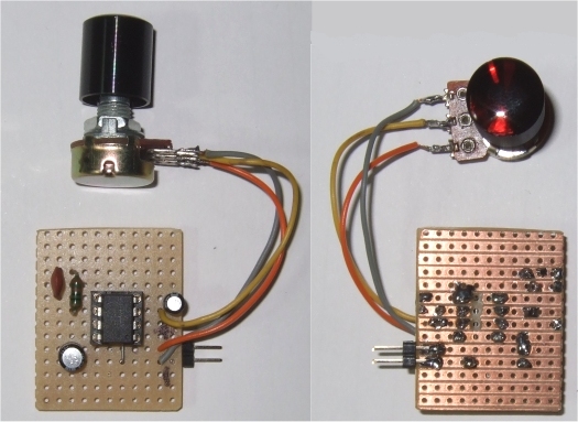
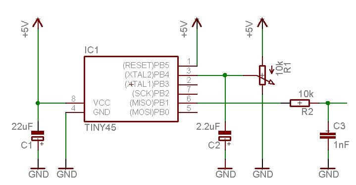
Fig 1: ATTiny45 test board top and bottom view and schematic
All ATTiny45 experiments use the above 1 sq. inch testboard, it could not get more simple than that, 1 potentiometer and 2 capacitors and a RC filter for the sine wave output. My chips work well with a voltage as low as 1.8 Volts, 2 batteries are enough to power the generators. The fuses in the ATTiny45 are set to use the internal RC oscillator at 8MHz, clockdiv8 is unchecked. The software used to compile the assembly code is gavrasm, which is freeware and has a small footprint and that's why I like to use it on the laptop.
Let's start with a sine wave generator
Features: ATTiny45, 1 potentiometer, linear frequency scale, range 15 Hz to 31 kHz
In a DDS there is a linear relationship between the word in the deltaphase and the frequency. So if the input voltage to the ADC is moved to the deltaphase word (Delta1, Delta2) after conversion then the frequency depends on the potentiometer setting in a linear way.
Output frequency (using a 16 bit accumulator Dds1 and Dds2) :Lets assume we need 8 cycles in a loop then we get f = Delta1,Delta2 * (clock/8)/65536, below the program's main loop:
f = deltaPhase * fClock / 2^16
where fClock = clock / LoopCycles, the microcontroller clock divided by the number of cycles to output the data
loop:With a 8 Mhz clock f = Delta1,Delta2 * 15.26 and the highest frequency is 15611 Hz. The 10 bit ADC gives values between 0..1023 so we get 15.26 * 1023 = 15611 Hz. Nice to see that the loop runs at 1 Mhz so every 1 us 1 byte is send to the output. It takes 256 us to output a full wave form, using a 256 byte lookup table.
add Dds1, Delta1
adc Dds2, Delta2
lpm
out OCR1A, r0 ; sine wave pwm
rjmp loop ; 8 cycles
The lookup table in the flash memory contains the amplitude information. This makes it quite flexible, whatever is in the lookup table be it a sine or a triangle wave form will be output on the OC1A pin PB1. Timer 1 is in pwm mode and clocks at 230 kHz when the PLL in the chip is enabled. A simple RC filter with 10k and 1 nF does the job, but could be done better as you can see.
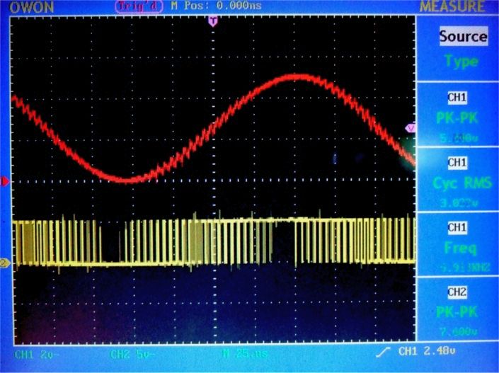
Fig 2: Scope trace, lower shows pwm, upper shows RC filtered sine wave output
You will ask where do we read the ADC to get the deltaphase? This is done in an interrupt which fires every 30 ms and takes about 100 us to get a new ADC result. The loop frequency and the interrupt timing are not correlated so it's not a systematic error but it will add phase noise to to the output. It's certainly not HiFi, the amplitude is quantized in 256 steps and the frequency setting has some granularity. Anyway I found it useful for a quick check of an audio amplifier over the full range.
The final program uses a little trick to double the the frequency, the last ADC value and the current one are added and so the deltaphase has values 0..2046. Then we get a frequency range from 15 Hz to 31 kHz. It also contains a sweep mode, when Pinb2 is pulled low it will start to sweep.
The program contains two other tables which output either a sawtooth or an inverted sawtooth at PB1. To activate the sawtooth table load ldi ZH,high(2*Sawtooth) and ldi ZL,low(2*Sawtooth) and compile. An easy way to lower the frequency range is to move the ADC reading into the loop, see below.
download: 45dSin1.asm
Program for a stroboscope
Features: ATTiny15/13, 1 potentiometer, linear frequency scale, range 1 Hz to 570 Hz
Even using a ATTiny15 we can put reading of the ADC in the main loop, however reading the ADC in the loop takes time and this limits the output frequency. Still it is useful to build a stroboscope which can measure up to 30000 rpm. The lookup table contains a square wave with different duty cycles on PB0..4 it is 50% on PB0, 25% on PB1, 12.5% on PB2 and 6% on PB3. These duty cycles remain unchanged when the frequency is varied. I have connected the PB2 output to a transistor driving a bright green LED which illuminates the target.
Using a ATTiny15/13 requires a slightly different hardware and software. The potentiometer wiper is connected to ADC3 which is PB4 and pin 2 of the chip, in the AT45 PB4 is pin 3 and ADC2, slightly confusing the way Atmel changed that.
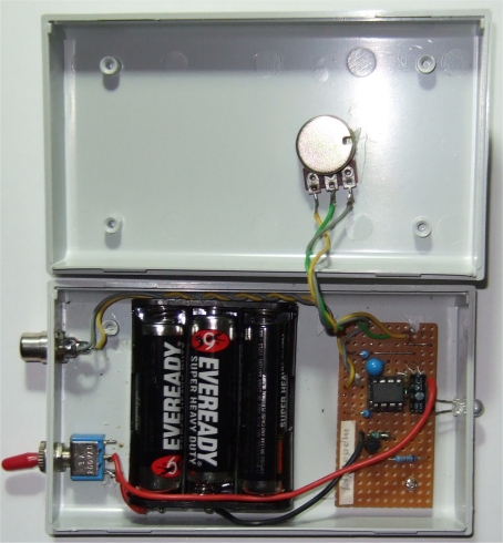
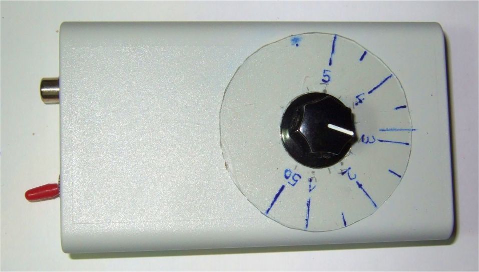
Fig3: stroboscope in a box, left on-off switch and output to measure frequency,
the LED is on the other end, linear scale
You can try to use a cheap laser pointer instead, I did at one time but it was too cheap and did not last long so went back to use a LED.
The program contains another table which gives a phase shifted square wave output, e.g. PB0 and PB2 have a 90 degrees phase shift over the frequency range. Duty cycle is 50%. To activate this table, load ldi ZH,high(2*phsquare) and ldi ZL,low(2*phsquare) and compile.
download: 15dStrobo.asm
Download: 13Strobo.zip
square wave generator
Features: ATTiny45, 1 potentiometer, linear frequency scale, range 15 Hz to 17.8 kHz (PB3)
Square waves can be generated without a lookup table. Lets see how that works.
LOOP1: ; Dds loopThe main loop increments the 16 bit dds accumulator and transforms the (linear) phase information to the binary output. In this case the dds accumulator is used directly, i. e. it is swapped and the upper 4 bit are send to the output port. At the port are 4 frequencies at the same time, like a binary counter.
add Dds1,Delta1 ; 1
adc Dds2,Delta2 ; 1
mov temp, Dds2 ; 1
swap temp ; 1
out PORTB, temp ; 1
rjmp LOOP1 ; 2 => 7 cycles
PB0: output f*8
PB1: output f*4
PB2: output f*2
PB3: output f
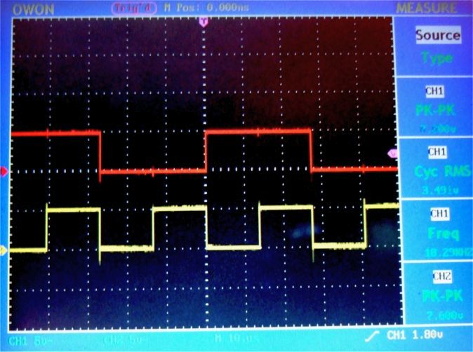
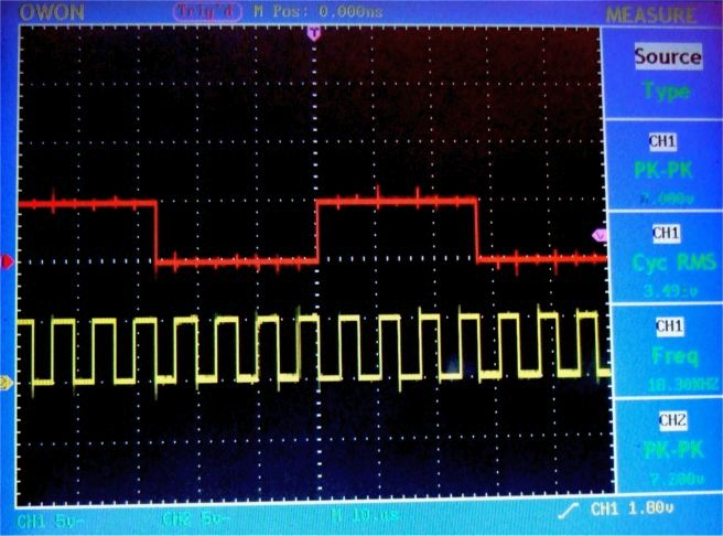
Fig4: Scope traces, upper is output PB3, lower is PB2 on the left and PB1 on the right
The same trick as in the sine wave generator is used, the ADC is read in Timer 1 interrupt and the result is transferred to Delta1 and 2. The loop needs only 7 cycles so we get f = Delta1,Delta2 * (clock/7)/65536, f = Delta1,Delta2 * 17.44 @ 8Mhz which gives a maximum frequency of 17840 Hz. at PB3 or 142 kHz at PB0. The scale is linear and it's quite an experience to turn the potentiometer and get a frequency from zero to 142 kHz.
download: 45dSQ5.asm
Any of these circuits can be used as a linear voltage to frequency converter. Instead of the potentiometer connect the input voltage to the ADC.
Here you have seen that these useful frequency generators don't need much hardware and only a little software. Feel free to experiment with the hardware and the software to make it work for your applications.
References
Wikipedia info: http://en.wikipedia.org/wiki/Direct_digital_synthesizer and http://en.wikipedia.org/wiki/Numerically-controlled_oscillator
Gerd's AVR assembler version 2.7: http://www.avr-asm-tutorial.net/gavrasm/index_en.html
Jesper Hansen's software: http://www.myplace.nu/avr/minidds/