
Clap Switch with ATtiny15
This is a remote control which is using sound to switch a load. Clap your hands twice in a time window and the light goes on like magic.
A microcontroller allows a bit more control and error handling than conventional circuits. A microphone and the transistor pre-amplifier convert the sound to an electrical signal. This is basically the clap frequency of more or less 2 kHz which is measured with TC0 at input PB2. TC1 provides the time base for the whole circuit and here uses 100 ms gate time to measure the clap frequency. The red led3 turns on when a sound is present.
Now the number of pulses which are counted with TC0 are compared to two thresholds. This should avoid a false trigger and seem to work quite well. The definition .equ tooshort= 8 means count pulses are too few, may be a spike only, and .equ toolong= 180 means count is too long, it could be noise etc. TC0 counts between 8 and 180 are considered a valid clap signal and set a flag for the first accepted clap. The blue led1 turns on.
Now it waits for waitclap= 60 i.e. 600 ms then listens for the second clap. The time window is cwindow= 250, a window of 2.5 sec to receive the 2nd clap. If this 2nd is also a valid clap then the output PB4 is turned on and the relais switches. To avoid switching by the click of the relais there is a blocktime= 4 meaning 4 seconds sounds are blocked when the relais has switched. During this time the red led3 is blinking, led4 turns on. Now, if you clap twice again the relais turns off. Lights off, magic again.
These parameters can be changed in the program according to your own experiments. The waitclap time could be a bit shorter.
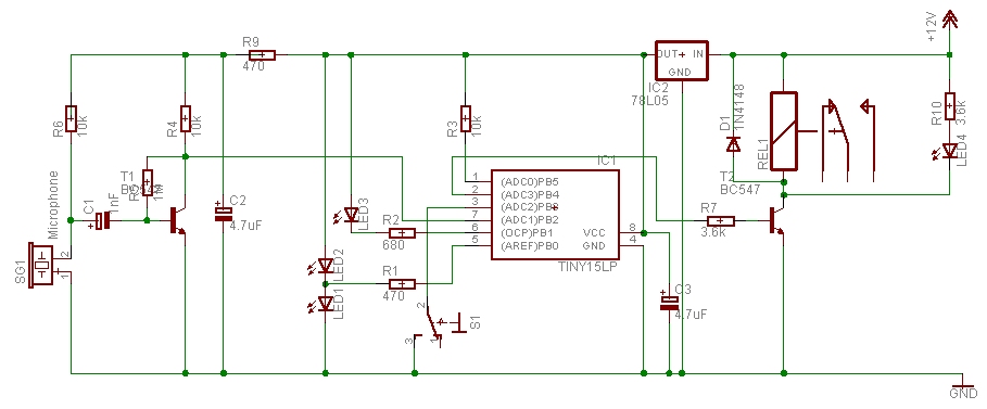
The circuit diagram of the clap switch. S1 is an optional manual push button and can turn the relais on or off.
When the program is waiting, the white led2 is on and the blue led1 blinks
once per second to show it is ready. This trick to switch 2 leds witch one output
pin works best with white and blue or green leds.
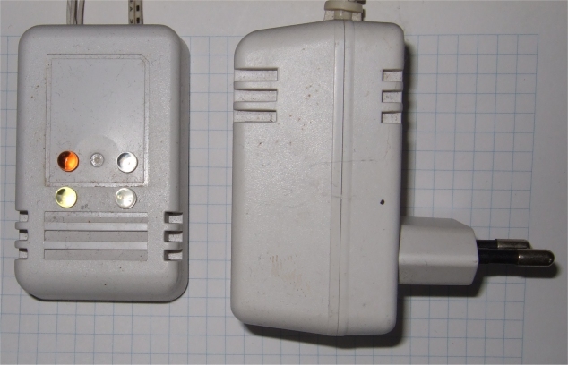
I have built different versions, in the one above PB4 is driving a power FET. The FET will turn on small 12V led lamps directly, no relais is used. That is why it can fit in a small box. The power supply is a simple wall plug for 12V DC and 300 mA.

One of the led lamps with sun-white leds.
All children will like this clap switch, it's fun to use.
download Klapp3.zip
This program is distributed in the hope that it will be useful but WITHOUT ANY WARRANTY;
References
Atmel datasheet ATtiny15, Atmel.com
Gerd's AVR assembler version 3.3: http://www.avr-asm-tutorial.net/gavrasm/index_en.html
;***************************************************************************
; AT15  Clap switch
;	Clap Clap switches Relais on or off
;	microphone input on PB2, T0 measures clap pulses
;	manual switch on PB3
; 	ATtiny15 GS 11-2009
;	The timing is adapted for 1.6 MHz
;
;  This program is free software; you can redistribute it and/or
;  modify it under the terms of the GNU General Public License.
;  This program is distributed in the hope that it will be useful,
;  but WITHOUT ANY WARRANTY;
;
;***************************************************************************
;			ATtiny15 dip
;	(RESET/ADC0) 	PB5	VCC
;	(ADC3) 		PB4	PB2 (ADC1/SCK/T0/INT0)
;	(ADC2) 		PB3	PB1 (AIN1/MISO/OC1A)
;			GND	PB0 (AIN0/AREF/MOSI)
;
;***************************************************************************
; PB4	output 	Relais act high
; PB3	input	pull up, manual toggle switch
; PB2	input	T0 counter
; PB1	output	Led3 act low
; PB0	output	2 Leds  + led--R--led -
;***************************************************************************

.DEVICE ATtiny15	;for gavrasm

; PB0 plex 2 Leds
.equ	Led3		= PB1
.equ	Input		= PB2
.equ	toggle		= PB3
.equ	Relais		= PB4

.equ	tooshort	= 8	; count too short, not valid
.equ	toolong		= 180	; count too long, noise etc
.equ	waitclap	= 60	; 600 ms between 2 claps
.equ	cwindow		= 250	; window 2.5 sec for 2nd clap
.equ	blocktime	= 4	; 4 seconds blocked after relais switched

.def	S		= r4
.def	zero		= r5

.def	temp		= r16
.def 	countL		= r17	; main timing
.def	countH		= r18
.def 	counter		= r19
.def 	upcnt		= r20
.def	Cnt0count	= r21	; Counter0 result
.def	ClapCnt		= r22	;
.def 	flag		= r23

.cseg
.org 0
; Reset-vector to adress 0000
	rjmp	reset
	reti 			; INT0addr= 0x0001	 External Interrupt 0
	reti 			; PCI0addr= 0x0002  	 pin Interrupt
	rjmp	TIM1_Cmp	; OC1addr = 0x0003 	 Timer/Counter1 Compare Match
	reti		 	; OVF1addr= 0x0004	 Timer/Counter1 Overflow
	reti			; OVF0addr= 0x0005	 Timer/Counter0 Overflow
	reti 			; ERDYaddr= 0x0006	 EEPROM Ready
	reti 			; ACIaddr=  0x0007 	Analog Comparator
	reti 			; ADCCaddr= 0x0008  	ADC Conversion Ready

;********************************************************************
;* "TIM1_Cmp" - Timer/counter 1 Compare Match interrupt handler
;*
;* interrupts every 10 ms, 40 x 250
;*
;********************************************************************
TIM1_Cmp:	in	S,sreg			; Updated every 10 ms, calibrate OSCCAL

		;sbis	PINB,  toggle		; skip if set
		;sbi	PORTB, toggle		; set output PORTB, PINB0
		;sbic	PINB,  toggle	 	; skip if set
		;cbi	PORTB, toggle

		;inc 	upcnt
		;cpi	upcnt, 100
		;brlo	TIM1_1			; 1 sec
		;clr	upcnt
		;dec 	ClapCnt			; dec slowly
		;brne	TIM1_1			; if 0
		;clr 	ClapCnt			; keep on 0

TIM1_1:		inc	counter			; use to delay
		inc	countL			; main timing
		brne	TIM1_ex
		inc	countH
TIM1_ex:	out	sreg,S
		reti
;***************************************************************************
reset:
		; writing the calibration byte to the OSCCAL Register.
		ldi	temp,0x72    		; not really needed
		out	OSCCAL,temp 		; for the clock
		nop
		clr	zero
; Port B
		ldi	temp,0b00001010	 	; set
		out	PORTB,	temp		; 1 = pull-up , 0 = float
		ldi	temp,0b00010011		; 1 = output , 0 = input
		out	DDRB,	temp       	; data direction register


;***************************************************************************
; timer1 setup:
		;Timer/Counter1 Overflow Interrupt Enable
		ldi	temp,0b01000000 	; set Bit compare match interrupt
		out	TIFR,temp 		; clear pending Interrupt
		out	TIMSK,temp 		; set in the Timer Interrupt Mask Register
		out	TCNT1,zero		; Timer/Counter 1 clear
		ldi	temp,250-1		; Timer/Counter 1 for 10 ms
		out	OCR1A,temp		; Bit 7 – CTC1: Clear Timer/Counter on Compare Match
		ldi	temp,0b10001011		; Timer/Counter 1 clocked at CK/64 = 40 us
		out	TCCR1,temp		; 1,6 Mhz

; timer0 setup:
		out	TCNT0,zero		; Timer/Counter 0 clear
		;ldi	temp,0b00000111		; Timer/Counter 0 external clock PB2 raising edge
		out	TCCR0,zero		; stop now

		sbi	AcsR,	Acd		; Disable Comparator

		cbi	PORTB, Relais
		sei				; Enable gobal iterrupt

;***************************************************************************

; test Leds at start
		cbi	PORTB, Led3		; on
		rcall	BlinkLed		; delays 300 ms
		rcall	BlinkLed
		rcall	BlinkLed
		sbi	PORTB, Led3		; off
		rcall	Ledoff

		clr	counter			; reset counter
		rcall	Led1
wait1led:
		cpi	counter, 50		; 500 ms
		brlo	wait1led
		rcall	Ledoff

		clr	counter			; reset counter
		rcall	Led2
wait2led:
		cpi	counter, 50		; 500 ms
		brlo	wait2led
		rcall	Ledoff


; wait for signal
main:
		sbic	PINB,Input		; If Input is
		rjmp	detecthi		;  high   - jump to detecthi

		sbis	PINB,toggle		; If toggle switch is
		rjmp	Rtoggle			;  low   - jump to Rtoggle

		cpi	countL, cwindow		; window 2.5 sec
		brlo	main
		clr	flag			; reset flag
		rcall	Led1			; blue

		rjmp	main			; Input low    - jump to main, wait for high
detecthi:
		cbi	PORTB, Led3		; on
		rcall	Ledoff
		inc	ClapCnt			; count line high
		sbrc	flag, 7			; 0 = first time
		rjmp	clrcnt			; 1 = 2nd time
		clr	countL			; reset main sw counters
		clr	countH			; 10 ms
clrcnt:		out	TCNT0,zero		; Timer/Counter 0 clear
		ldi	temp,0b00000111		; Timer/Counter 0 external clock PB2 rising edge
		out	TCCR0,temp		; start Timer/Counter 0 counting now
		clr	counter			; reset counter
wait1st:
		cpi	counter, 10		; 100 ms count pulses
		brlo	wait1st
		sbi	PORTB, Led3		; off

		in	Cnt0count, TCNT0	; get counter 0 counts

		out	TCCR0,zero		; stop now
		out	TCNT0,zero		; Timer/Counter 0 clear
						; now check no of signals counted
		cpi	Cnt0count, tooshort	; count too short, not valid
		brsh	m1			; filter spikes
		rcall	Led1			; blue
		clr 	flag
		rjmp	main

m1:		cpi	Cnt0count, toolong	; cnt ok 8 - 180
		brsh	m2
		rcall	Led2			; white Led is on
		inc	flag
		sbr	flag, 0x80		; bit 7 indicates first time ok
		rjmp	wait2nd

m2:						; cnt too high, noise etc.
		clr 	flag
		rcall	BlinkLed		; delays 200 ms
		rcall	BlinkLed
		rcall	BlinkLed
		rjmp	main

wait2nd:
		cpi	counter, waitclap	; 60 = 600 ms between claps
		brlo	wait2nd
		rcall	Ledoff
		rcall	Led2			; white

		;cpi	ClapCnt, 30		; check if too many signals
		;brsh	waitblock		; block then


waitsee:	cpi	flag, 0x82		; 2 claps and 2nd time
		brne	main

Rtoggle:	sbis	PINB,  Relais		; toggle Relais
		sbi	PORTB, Relais		; PORTB
		sbic	PINB,  Relais	 	; skip if set
		cbi	PORTB, Relais
		clr 	flag
		rcall	Ledoff

waitblock:
		sbrs	counter, 4		; use counter to blink
		rjmp	wbLedoff		; while waiting
		cbi	PORTB, Led3		; on
		rjmp	wbCont
wbLedoff:
		sbi	PORTB, Led3		; off

wbCont:
		cpi	countH, blocktime	; block some seconds
		brlo	waitblock		; after toggle Relais

		sbi	PORTB, Led3		; off
		rcall	Ledoff
		rjmp	main


;***************************************************************************
; plex 2 Leds on PB 0
Led1:		; blue
		sbi	PORTB,	PB0		; high
		sbi	DDRB,	PB0       	; output
		ret
Led2:		; white
		cbi	PORTB,	PB0		; low
		sbi	DDRB,	PB0       	; output
		ret
Ledoff:
		cbi	PORTB,	PB0		; low
		cbi	DDRB,	PB0       	; input
		ret

BlinkLed:
		sbi	PORTB,	PB0		; high
		sbi	DDRB,	PB0       	; output Led1
		clr	counter
Blink1:		cpi	counter, 10		; delay 100 ms
		brne	Blink1

		cbi	PORTB,	PB0		; low
		cbi	DDRB,	PB0       	; input Led off
		nop

		cbi	PORTB,	PB0		; low
		sbi	DDRB,	PB0       	; output Led2
		clr	counter
Blink2:		cpi	counter, 10		; delay 100 ms
		brne	Blink2

		cbi	PORTB,	PB0		; low
		cbi	DDRB,	PB0       	; input Led off
		ret