
by Ralf Beesner, DK5BU
Elektronik-Labor Projekte AVR
/* Name: main.c
License: GPL V2 (see /doc/GPL.txt)
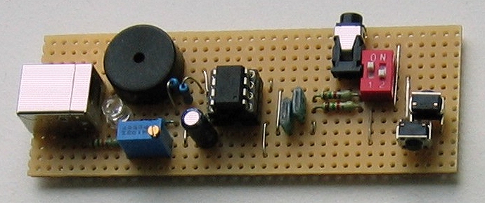
This is a special 1-key keyboard - it "understands" morse code
The average speed may be chosen by a switch (60 chars per minute or 90 chars per minute).
As the morse code has no characters for <return> and <blank>, three morse traffic abbreviations
are used:
Return: <kn>
Blank: <as>
TAB: <ab>
A second switch activates an autoSpace function. One Blank is inserted automatically after the
correct waiting time between two words has passed.
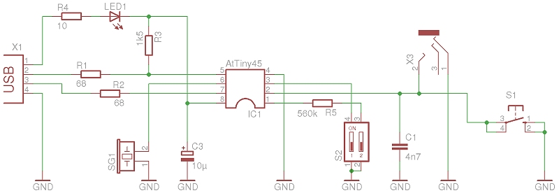
As all digital I/Os are in use already, we use the Analog Input at ADC0/Reset. Normaly the ADC
value is 255, but when the switch is closed, a 560 kOhm resistor pulls down the ADC0/Reset pin
a little, so that the ADC value will be below 250.
Attiny45 Pins
PB0 USB D -
PB1 (OC0B) Sidetone Buzzer
PB2 USB D +
PB3 Morse Key
PB4 Speed switch
The code emulates a German keyboard. To emulate an american keyboard, you have to change
#include "keyboard-de.h" to #include "keyboard-us.h"
* the code is based on Project: 4-Key-Keyboard (Author: Flip van den Berg - www.flipwork.nl)
* and using the V-USB drivers from Objective Developments - http://www.obdev.at/products/vusb/index.html
*/
/*
fuse settings for ATTiny45/85:
EXTENDED: 0xFF
HIGH: 0xDD
LOW: 0xE1
*/
#include <avr/io.h>
#include <avr/wdt.h>
#include <avr/eeprom.h>
#include <avr/interrupt.h>
#include <avr/pgmspace.h>
#include <util/delay.h>
#include <stdlib.h>
#include "usbdrv.h"
#include "hidkbd-de.h"
// #include "hidkbd-us.h"
#include "morsetable.h"
/* ------------------------------------------------------------------------- */
static uchar reportBuffer[8] = {0,0,0,0,0,0,0,0}; /* buffer for HID reports */
/* Reportbuffer format:
0 Modifier byte
1 reserved
2 keycode array (0)
3 keycode array (1)
4 keycode array (2)
5 keycode array (3)
6 keycode array (4)
7 keycode array (5)
<< This is the standard usb-keyboard reportbuffer. It allows for 6 simultaneous keypresses to be detected (excl. modifier keys). In this application we only use 1, so the last 5 bytes in this buffer will always remain 0. >>
<< I decided not to optimize this in order to make it easy to add extra keys that can be pressed simultaneously>>
Modifier byte: 8 bits, each individual bit represents one of the modifier keys.
bit0 LEFT CTRL (1<<0)
bit1 LEFT SHIFT (1<<1)
bit2 LEFT ALT (1<<2)
bit3 LEFT GUI (1<<3)
bit4 RIGHT CTRL (1<<4)
bit5 RIGHT SHIFT (1<<5)
bit6 RIGHT ALT (1<<6)
bit7 RIGHT GUI (1<<7)
an example of a reportBuffer for a CTRL+ALT+Delete keypress:
{((1<<0)+(1<<2)),0,76,0,0,0,0,0}
the first byte holds both the LEFT CTRL and LEFT modifier keys the 3rd byte holds the delete key (== decimal 76)
*/
static uchar idleRate;
static uchar newReport = 1;
static uchar modifier;
static uchar key;
/* ---------------------- morsepart ---------------------------------------- */
static uchar morseByte = 1;
static uchar serByte;
static uchar ditlen;
static uchar dahlen;
static uchar timeCnt;
static uchar state;
static uchar autoSpace;
static uchar ADCval;
#define tonefreq 112
static void morsedec(void){
if (state == 0){ // idle
timeCnt = 0;
if ((PINB & (1 << PB3)) == 0) { // key pressed, new morsechar starts
state = 1;
}
}
if (state == 1){ // morsechar has started
DDRB |= (1 << PB1); // buzzer on
if ((PINB & (1 << PB3)) != 0){ // key open, time for a dit has ended
if (timeCnt > ditlen){
state = 2;
morseByte = morseByte << 1; // shift charCode
}
else{ // this is for debouncing
DDRB &= ~(1 << PB1); // buzzer off
state = 0; // all to start
}
}
if ((PINB & (1 << PB3)) == 0){ // key pressed
DDRB |= (1 << PB1); // buzzer on
if (timeCnt > dahlen){ // time for a dah has ended
morseByte = morseByte << 1; // shift charcode
morseByte++; // dah -> lowest bit = 1
state = 2;
}
}
}
if (state == 2){ // this state means: dit is finished or dah still active
if ((PINB & (1 << PB3)) != 0){ // key open, dit or dah finished
DDRB &= ~(1 << PB1); // buzzer off
timeCnt = 0;
state = 3;
}
}
if (state == 3){
if ((PINB & (1 << PB3)) == 0){ // new dit or dah has started
state = 0;
}
if ((PINB & (1 << PB3)) != 0){ // key still open
if (timeCnt > dahlen){ // waiting time is greater than space between two morsechars
state = 4;
}
}
}
if (state == 4){ // morsechar complete
serByte = pgm_read_byte (&morsetable[morseByte]);
morseByte = 1;
DDRB &= ~(1 << PB1); // buzzer = 0
timeCnt = 0;
key = pgm_read_byte (&keycode[serByte]); // ascii to usb keycode
if (key > 128){ // values with shift modifier
key = key - 128;
modifier = 2;
}
else{
modifier = 0;
}
newReport = 0;
if (autoSpace > 0){
state = 5;
}
else{
state = 0;
}
}
if (state == 5){ // morsechar complete, autoSpace active
if ((PINB & (1 << PINB3)) != 0){ // keys still open
if (timeCnt > (dahlen*3 )){ // waiting time is greater than space between two morsechars
serByte = 32; // space
key = pgm_read_byte (&keycode[serByte]); // ascii to usb keycode
newReport = 0;
timeCnt = 0;
morseByte = 1;
state = 0; // ready!
}
}
else{ // if key is pressed
timeCnt = 0;
morseByte = 1;
state = 0; // ready!
}
}
}
/* ------------------------------------------------------------------------- */
PROGMEM char usbHidReportDescriptor[USB_CFG_HID_REPORT_DESCRIPTOR_LENGTH] = {
0x05, 0x01, // USAGE_PAGE (Generic Desktop)
0x09, 0x06, // USAGE (Keyboard)
0xa1, 0x01, // COLLECTION (Application)
0x05, 0x07, // USAGE_PAGE (Keyboard)
0x19, 0xe0, // USAGE_MINIMUM (Keyboard LeftControl)
0x29, 0xe7, // USAGE_MAXIMUM (Keyboard Right GUI)
0x15, 0x00, // LOGICAL_MINIMUM (0)
0x25, 0x01, // LOGICAL_MAXIMUM (1)
0x75, 0x01, // REPORT_SIZE (1)
0x95, 0x08, // REPORT_COUNT (8)
0x81, 0x02, // INPUT (Data,Var,Abs) ** Modifier Byte **
0x95, 0x01, // REPORT_COUNT (1)
0x75, 0x08, // REPORT_SIZE (8)
0x81, 0x03, // INPUT (Cnst,Var,Abs) ** Reserved Byte **
0x95, 0x05, // REPORT_COUNT (5)
0x75, 0x01, // REPORT_SIZE (1)
0x05, 0x08, // USAGE_PAGE (LEDs)
0x19, 0x01, // USAGE_MINIMUM (Num Lock)
0x29, 0x05, // USAGE_MAXIMUM (Kana)
0x91, 0x02, // OUTPUT (Data,Var,Abs) ** LED Report **
0x95, 0x01, // REPORT_COUNT (1)
0x75, 0x03, // REPORT_SIZE (3)
0x91, 0x03, // OUTPUT (Cnst,Var,Abs) ** LED Report Padding **
0x95, 0x06, // REPORT_COUNT (6) ** here we define the maximum number of simultaneous keystrokes we can detect **
0x75, 0x08, // REPORT_SIZE (8)
0x15, 0x00, // LOGICAL_MINIMUM (0)
0x25, 0x65, // LOGICAL_MAXIMUM (101)
0x05, 0x07, // USAGE_PAGE (Keyboard)
0x19, 0x00, // USAGE_MINIMUM (Reserved (no event indicated))
0x29, 0x65, // USAGE_MAXIMUM (Keyboard Application)
0x81, 0x00, // INPUT (Data,Ary,Abs) ** Key arrays (6 bytes) **
0xc0 // END_COLLECTION
};
static void buildReport(void){
if(newReport == 0){
reportBuffer[0] = modifier;
reportBuffer[2] = key;
}
if(newReport != 0){
reportBuffer[0] = 0;
reportBuffer[2] = 0;
}
}
/* -------------------------------------------------------------------------------- */
/* ------------------------ interface to USB driver ------------------------ */
/* -------------------------------------------------------------------------------- */
uchar usbFunctionSetup(uchar data[8])
{
usbRequest_t *rq = (void *)data;
usbMsgPtr = reportBuffer;
if((rq->bmRequestType & USBRQ_TYPE_MASK) == USBRQ_TYPE_CLASS){ /* class request type */
if(rq->bRequest == USBRQ_HID_GET_REPORT){ /* wValue: ReportType (highbyte), ReportID (lowbyte) */
/* we only have one report type, so don't look at wValue */
buildReport();
return sizeof(reportBuffer);
}else if(rq->bRequest == USBRQ_HID_GET_IDLE){
usbMsgPtr = &idleRate;
return 1;
}else if(rq->bRequest == USBRQ_HID_SET_IDLE){
idleRate = rq->wValue.bytes[1];
}
}else{
/* no vendor specific requests implemented */
}
return 0;
}
/* ------------------------------------------------------------------------- */
/* ------------------------ Oscillator Calibration ------------------------- */
/* ------------------------------------------------------------------------- */
/* Calibrate the RC oscillator to 8.25 MHz. The core clock of 16.5 MHz is
* derived from the 66 MHz peripheral clock by dividing. Our timing reference
* is the Start Of Frame signal (a single SE0 bit) available immediately after
* a USB RESET. We first do a binary search for the OSCCAL value and then
* optimize this value with a neighboorhod search.
* This algorithm may also be used to calibrate the RC oscillator directly to
* 12 MHz (no PLL involved, can therefore be used on almost ALL AVRs), but this
* is wide outside the spec for the OSCCAL value and the required precision for
* the 12 MHz clock! Use the RC oscillator calibrated to 12 MHz for
* experimental purposes only!
*/
static void calibrateOscillator(void)
{
uchar step = 128;
uchar trialValue = 0, optimumValue;
int x, optimumDev, targetValue = (unsigned)(1499 * (double)F_CPU / 10.5e6 + 0.5);
/* do a binary search: */
do{
OSCCAL = trialValue + step;
x = usbMeasureFrameLength(); /* proportional to current real frequency */
if(x < targetValue) /* frequency still too low */
trialValue += step;
step >>= 1;
}while(step > 0);
/* We have a precision of +/- 1 for optimum OSCCAL here */
/* now do a neighborhood search for optimum value */
optimumValue = trialValue;
optimumDev = x; /* this is certainly far away from optimum */
for(OSCCAL = trialValue - 1; OSCCAL <= trialValue + 1; OSCCAL++){
x = usbMeasureFrameLength() - targetValue;
if(x < 0)
x = -x;
if(x < optimumDev){
optimumDev = x;
optimumValue = OSCCAL;
}
}
OSCCAL = optimumValue;
}
/*
Note: This calibration algorithm may try OSCCAL values of up to 192 even if
the optimum value is far below 192. It may therefore exceed the allowed clock
frequency of the CPU in low voltage designs!
You may replace this search algorithm with any other algorithm you like if
you have additional constraints such as a maximum CPU clock.
For version 5.x RC oscillators (those with a split range of 2x128 steps, e.g.
ATTiny25, ATTiny45, ATTiny85), it may be useful to search for the optimum in
both regions.
*/
void hadUsbReset(void)
{
calibrateOscillator();
eeprom_write_byte(0, OSCCAL); /* store the calibrated value in EEPROM byte 0*/
}
/* ------------------------------------------------------------------------- */
/* --------------------------------- main ---------------------------------- */
/* ------------------------------------------------------------------------- */
int main(void)
{
uchar i;
uchar calibrationValue;
do {} while (!eeprom_is_ready());
calibrationValue = eeprom_read_byte(0); /* calibration value from last time */
if(calibrationValue != 0xff){
OSCCAL = calibrationValue;
}
usbInit();
usbDeviceDisconnect(); /* enforce re-enumeration, do this while interrupts are disabled! */
i = 0;
while(--i){ /* fake USB disconnect for > 250 ms */
wdt_reset();
_delay_ms(1);
}
usbDeviceConnect();
wdt_enable(WDTO_2S);
/* turn on internal pull-up resistors */
PORTB |= (1 << PB3) | (1 << PB4); // activates pullups PB3 and PB4
ACSR |= (1 << ACD); // analog comparator off
DIDR0 |= (1 << AIN1D); // deactivates digital input PB1
// Timer0 generates the morse tone at PB1 (OC0B)
TCCR0A |= (1 << COM0B1) | (1 << WGM01) | (1 << WGM00) ; // fast PWM at OC0B Pin, maximum value = OCR0A
TCCR0B |= (1 << WGM02) | (1 << CS02) ; // Prescaler / 256
OCR0A = tonefreq;
// Timer1 init
TCCR1 = 0x09; // select clock: 16.5M/256 -> overflow rate = 16.5M/(256*256) = 252 Hz -> 4 ms
ADMUX = 0x20; // select ADC channel (ADC0) / PB5 (Reset), 8 bit resolution
ADCSRA |= (1 << ADEN) | (1 << ADSC) | (1 << ADATE) | (1 << ADPS2); // ADC enabled, free running, clock prescaler / 16
_delay_ms(100); // waiting for high level to arrive at PB3
sei();
for(;;){ // main event loop
wdt_reset();
usbPoll();
if ((PINB & (1<<PB4)) == 0){ // lowest possible speed 60 chars / minute , 50 ms ditlen
ditlen = 12; // 12*4 ms
dahlen = 36;
}
else{ // lowest possilbe speed 40 chars / minute -> 75 ms ditlen
ditlen = 18; // 18*4 ms
dahlen = 54;
}
ADCval = ADCH; // 166 ... 255
if (ADCval < 250){
autoSpace = 1; // ditLen 90 ... 0
}
else{
autoSpace = 0;
}
if ((TIFR & (1 << TOV1)) != 0){ // Timer1 Overflow
TIFR |= (1 << TOV1); // Resets Timer1
timeCnt++;
morsedec();
}
if(usbInterruptIsReady() && newReport == 0){ // we may send another report
buildReport();
usbSetInterrupt(reportBuffer, sizeof(reportBuffer));
newReport = 1;
}
if(usbInterruptIsReady() && newReport == 1){ // we send an empty report to stop repetitions
buildReport();
usbSetInterrupt(reportBuffer, sizeof(reportBuffer));
newReport = 2; // we silence USB reports
}
}
return 0;
}