TV-Simulator mit Tiny2313
von Gerd Sinning
Dieser
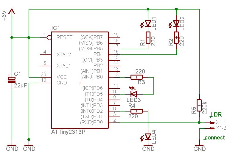
TV-Simulator mit einem ATtiny2313 macht nichts anderes als die LEDs
zufällig blinken zu lassen. Eine Steuerung über einen LDR schaltet ihn
nur ein, wenn es dunkel ist und am Tag wieder aus, d.h. er läuft die
ganze Nacht. Damit simuliert er einen Betrachter, der vor dem Ferseher
eingeschlafen ist, nicht unrealistisch bei dem Fernsehprogramm.
Durch intensives Recycling von Programmcodes war das relativ schnell zu programmieren. Der Zufallsgenerator stammt aus dem Noisegenerator
mit dem ATtiny13 und wurde auf den ATtiny2313 angepasst. Alle Ports bis
auf den Eingang für den LDR sind Ausgänge, die die LEDs ansteuern
können. Auch Querverbindungen wie z.B. zwischen PB0 und PD5 sind
möglich, dann hat man eine Und-Verknüpfung: die LED leuchtet nur, wenn
PB0 high ist und PD5 low ist. Das ergibt ganz nette Lichteffekte. Die
Blinkrate kann mit c_value = 19999 ; Compare value for compare
interrupt 20 ms verändert werden. Die Tag/Nacht Steuerung mit dem LDR
stammt aus dem Nightlight
Projekt. Die benutzt eine Hysterese, die über die Zeit gesteuert wird,
damit in der Dämmerung nicht immer ein- und ausgeschaltet wird. Mit
Lightdelay = 3 ; seconds before switch on kann man das anpassen. Für
einen TV-Simulator vielleicht unnötig und sieht in Assembler auch
ziemlich wuselig aus, funktioniert aber gut.
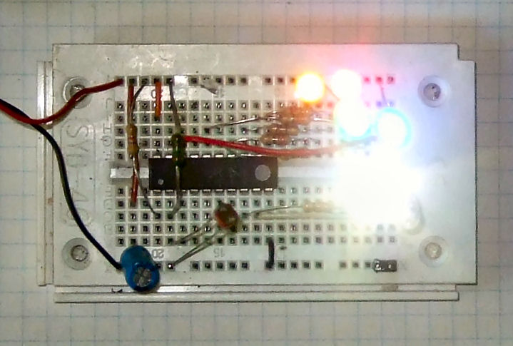
Die
vielen LEDs verbrauchen viel Strom, deshalb wird der TV-Simulator hier
mit einem kleinen 5V-Steckernetzteil betrieben. Das ist auch für eine
Disco-Gartenparty geeignet.
Download: TV2313.zip
;***************************************************************************
;
; ATtiny2313  Pseudonoise generator
;							TV simulator
;
; 39 bit maximal length generator. Repeats every 549,755,813,887 cycles
; at 200,000 Hz the repeat is 2.748.779,07 seconds, or
; 763 hours, or 32 days(!)
;
; GS May-2010 - 2013, based on ATtiny15 noiseG3.asm
; original code see eof
;
;  This program is free software; you can redistribute it and/or
;  modify it under the terms of the GNU General Public License.
;  This program is distributed in the hope that it will be useful,
;  but WITHOUT ANY WARRANTY;
;
;***************************************************************************
; The timing is adapted for 1 MHz
;***************************************************************************
;
;                 ATiny2313  PDIP
;
; (RESET/dW) 	  PA2 1   20 VCC
; (RXD) 	 		 	PD0 2   19 PB7 (UCSK/SCK/PCINT7)
; (TXD) 	  		PD1 3   18 PB6 (MISO/DO/PCINT6)
; (XTAL2) 	  	PA1 4   17 PB5 (MOSI/DI/SDA/PCINT5)
; (XTAL1) 	  	PA0 5   16 PB4 (OC1B/PCINT4)
; (CKOUT/XCK/INT0)PD2 6   15 PB3 (OC1A/PCINT3)
; (INT1) 	 			PD3 7   14 PB2 (OC0A/PCINT2)
; (T0)	 		  	PD4 8   13 PB1 (AIN1/PCINT1)
; (OC0B/T1) 	 	PD5 9   12 PB0 (AIN0/PCINT0)
;	 GND						 10 	 11 PD6 (ICP)
;
;***************************************************************************
;
; LDRin		= PIND0		 + R LDR Gnd, low is day
; PORTB output for Leds PB0..7
; PORTD output for Leds PD1..6
;
;***************************************************************************

.DEVICE ATtiny2313	;for gavrasm V3.3
;
;***************************************************************************
;Register Definitions
;***************************************************************************
;
.def	STEMP		= R1	;
.def	PN_A		= R2	;7-0
.def	PN_B		= R3	;15-8
.def	PN_C	 	= R4	;23-9
.def	PN_D		= R5	;-24
.def	PN_E		= R6	;
.def	PN_F		= R7	;
.def	PN_G		= R8	;
.def  zero		= r9
.def	TEMP		= r16	;
.def	TEMP2		= r17	;
.def	ITEMP		= r18	;
.def	ITEMP2	= r19	;
.def	countL	= r20
.def	count		= r21
;
;
;***************************************************************************

.equ	LDRin		= PIND0							; in + R LDR Gnd, low is day
.equ Clock		= 1000000
.equ c_value	= 19999							; Compare value for compare interrupt 20 ms
.equ s_value	= Clock/(c_value+1)	; Compare value for 1 second
.equ	Lightdelay	= 3							; seconds before switch on

;***************************************************************************
.cseg
.org 0
; ***** INTERRUPT VECTORS **************************************************
		rjmp	reset
.org OC1Aaddr				;  compare A interrupt vector
		rjmp	OC1A
;
;***************************************************************************
; compare A interrupt
;***************************************************************************
OC1A:
		in		STEMP,SREG	; Get Status bits
;		sbi		PORTB,toggle	; DEBUG Show we are in the ISR


		;Generate the feedback from bits 39,35 (NOTE! Hill uses 1,2,3,4 numbering)
		clr		ITEMP		;
		clr		ITEMP2		;
		sbrc	PN_E,6		;39
		sbr		ITEMP,1<<0	;XXXXXXXA
		sbrc	PN_E,2		;35
		sbr		ITEMP2,1<<0	;XXXXXXXB
		eor		ITEMP2,ITEMP	;Xor
		ror		ITEMP2		;Put bit 0 in carry

		;Shift everyone over, and the carry into the register.
		;104 bits long. If you use maximal length, this will last
		;way longer than the universe.

						;Bits   Hill's bits
		rol		PN_A		;7-0     8-1
		rol		PN_B		;15-8    16-9
		rol 	PN_C		;23-16   and so on
		rol		PN_D		;31-17
		rol		PN_E		;39-32   40-33
		rol		PN_F		;47-40


		;Output the bits
		out PORTB, PN_A
		out PORTD, PN_E

		inc	count							; count up
		cpi count, s_value		; 100 * 10 ms = 1 s
		brlo	OC1Ab
		clr	count

OC1ALight:
		sbis	PIND, LDRin						; skip if LDRin high, night
		inc 	countL								; lo is day
		cpi	countL, Lightdelay			; delay sec day
		brsh	OC1Aday
		sbic	PIND, LDRin						; skip if LDRin lo, day
		inc 	countL								; lo is day
		cpi	countL, Lightdelay			; delay sec nite
		brsh	OC1ANite
		rjmp	OC1Ab
OC1ANite:
		clr 	countL
 		out   PORTB,zero
 		ldi   temp,0xFF					;switch on
 		out   DDRB,temp
		out 	PORTD,zero				;
		ldi 	temp,0b11111110		;PD0 = LDR
		out 	DDRD,temp					;output
		rjmp	OC1Ab

OC1Aday:
		clr 	countL
 		out   PORTB,zero   			;switch off
 		out   DDRB,zero
		out 	PORTD,zero				;
		out 	DDRD,zero					;output

OC1Ab:
		out	SREG,	STEMP	; Restore Status bits
		reti					;
;
;***************************************************************************
reset:
			; writing the calibration byte to the OSCCAL Register.
			;ldi	temp,0x7A    		; config val
			;out	OSCCAL,temp 		; for the cpu clock
			;nop
			;nop
   		;ldi   temp,0b10000000		; clock prescaler change enable
   		;out		CLKPR,temp
    	;ldi   temp,0b00000000		; clock prescaler set to 0
   		;out		CLKPR,temp
   		;nop				; wait a little when switching
   		;nop

			ldi		temp, RAMEND
			out		SPL, temp		; setup stack pointer

   		out   PORTB,zero
   		ldi   temp,0xFF
   		out   DDRB,temp
			out 	PORTD,zero				;
			ldi 	temp,0b11111110		;PD0 = LDR
			out 	DDRD,temp					;output

   		sbi		ACSR, ACD					; turn off analog comp.


	; timer 1
			ldi 	temp,high(c_value)	; Load compare high value
			out	OCR1AH,temp
			ldi 	temp,low(c_value)	; Load compare low value
			out	OCR1AL,temp		; timing 1 ms @ 4 MHz

			ldi 	temp,0x00
			out 	TCNT1H,temp		;Clear timer high byte
			out 	TCNT1L,temp		;Clear timer low byte
			out 	TCCR1A,temp		;Clear timer control reg A
			ldi 	temp,0x40			;TOV1 OCF1A OCF1B – ICF1 OCF0B TOV0 OCF0A: TIFR
			out		TIFR,temp			;Clear pending timer interrupt
			out		TIMSK,temp		;Enable Timer 1 compare interrupt
							;TOIE1 OCIE1A OCIE1B – ICIE1 OCIE0B TOIE0 OCIE0A: TIMSK
			ldi 	temp,0b00001001		;0x9
			out 	TCCR1B,temp		;Clear timer on compare match,CK/1

			ldi	TEMP,$55		; Init the PN generator
			mov	PN_A,TEMP		;
			mov	PN_B,TEMP		;
			mov	PN_C,TEMP		;
			mov	PN_D,TEMP		;
			mov	PN_E,TEMP		;
			mov	PN_F,TEMP		;

			sei				; enable interrupts
Idle:						;
		rjmp	Idle			; That's all we do.
;

;***************************************************************************

;Some other two tap point SR combinations, from Art of Electronics
;Note, hill counts bits as 1,2,3,4, not 0,1,2,3
;Tap points  	 Length
;3,2	              7
;4,3	             15
;5,3	             31
;6,5	             63
;7,6	            127
;9,5	            511
;10,7	          1,023
;11,9	          2,047
;15,14	         32,767
;17,14	        131,071
;18,11	        262,143
;20,17	      1,048,575
;21,19	      2,097,151
;22,21	      4,194,303
;23,18	      8,388,607
;25,22	     33,554,431
;28,25	    268,435,455
;29,27	    536,870,911
;31,28	  2,147,483,647
;33,20	  8,589,934,591
;35,33	 34,359,738,367
;36,25	 68,719,476,735
;39,35	549,755,813,887
;
;A 100 bit register, clocked at 10 mHz would outlast the age
;of the universe, by 1,000,000 times.
;
;***************************************************************************
; Noisy Box     M A I N   M O D U L E
;
; Date				;6/30/04
; Version			:1.00
; Support telephone	:765 287 1989  David B. VanHorn
; Support Email		:dvanhorn@cedar.net
; Target MCU		:Atmel Tiny-11
;
; DESCRIPTION
;
; Pseudonoise generator, output on B0.
;
;***************************************************************************