
Timer with ATtiny15/13
This is a simple timer which I'm using to charge batteries, because I have a tendency to forget about the batteries and then they get overcharged. No good.
The time can be set with a potentiometer between 1 minute and 1023 minutes, about 17 hours. A pushbutton starts the time, turns on a relais and the timer will turn off the relais when the time is elapsed. It can be switched to seconds for a shorter time period (17 minutes) e.g. to boil eggs, also easy to forget about.
The ATTiny15 is using an internal oscillator only and needs a calibration for a 10 ms high pulse on PB1, so it is necessary to write a good calibration byte to the OSCCAL register, which is in the beginning of the program OSCCAL_val= 0x6F. It's a bit of trial and error until the 10 ms are set for your contoller but is should be done. The total time is not extremely accurate because we can't use a quartz, but for a battery charger I think it is good enough, the batteries don't mind a few minutes more or less. However, time setting with a potentiometer is quick and easy.
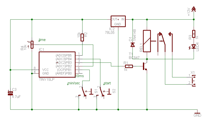
The circuit diagram, S1 is a switch min/sec which you may need or not, and S2 is a pushbutton to start the timer.
If 17 hours are not sufficient and a longer time is required it is possible to change the value of cnt_cmp = 100 ; 100 * 10 ms = 1 second in the program to e.g. cnt_cmp = 200, which will double the time to 34 hours. Depending on your application the time can also be much shorter, change cnt_cmp accordingly.
Any high to low transition on PB4 will start the timer, even a LDR could be connected to PB4 to make a light switch which turns on for the preset time when it is dark. It will turn off even if PB4 is still low and then waits for the switch or LDR to go high again. This also prevents a false trigger when the time is short and the button is still pressed. It is quite flexible and can be adapted to many applications which need a timer.
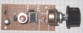
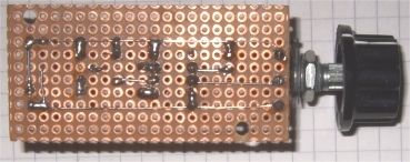
A possible layout of the board, top and bottom view. (the test setup before it went into the box)
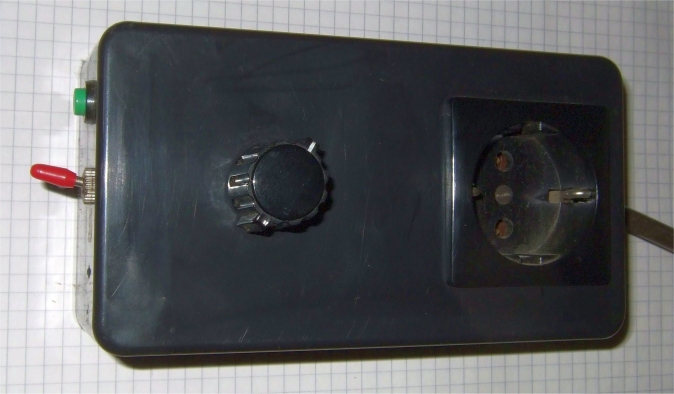
The timer in a box.
It was quite easy to make and since then I'm using it whenever the batteries need charging.
download AT15timer1.asm
Tiny13-Version, Beitrag zum T13-Contest: AT13timer1.zip
This program is distributed in the hope that it will be useful but WITHOUT
ANY WARRANTY;
References
Atmel datasheet ATtiny15, Atmel datasheet ATtiny13, Atmel.com
Gerd's AVR assembler version 2.7: http://www.avr-asm-tutorial.net/gavrasm/index_en.html
For a Scope can use: VA -- Visual Analyzer http://www.sillanumsoft.org
;***************************************************************************
; AT15  timer 1-1023 minutes (17 h), 0 = 1 min
;	ADC channel 1, potentiometer to set time
;	switch hi=minutes, lo=seconds (17 min)
;	pbStart switch Relais on , Relais off after time elapsed
; 	ATtiny15 GS 11-2009
;	The timing is adapted for 1.6 MHz
;
;  This program is free software; you can redistribute it and/or
;  modify it under the terms of the GNU General Public License.
;  This program is distributed in the hope that it will be useful,
;  but WITHOUT ANY WARRANTY;
;
;***************************************************************************
;			ATtiny15 dip
;	(RESET/ADC0) 	PB5	VCC
;	(ADC3) 		PB4	PB2 (ADC1/SCK/T0/INT0)
;	(ADC2) 		PB3	PB1 (AIN1/MISO/OC1A)
;			GND	PB0 (AIN0/AREF/MOSI)
;
;***************************************************************************
; PB0	output	toggle pin (calibrate 10 ms)
; PB1	input   switch hi=minutes, lo=seconds
; PB2	input   ADC channel 1 potentiometer to set time
; PB3	output  active high Relais
; PB4	input	start pushbutton (to lo)
;***************************************************************************

.DEVICE ATtiny15	;for gavrasm

.equ	toggle		= PB0
.equ	swMinSec	= PB1
;ADC1 = PB2
.equ	Relais		= PB3
.equ	pbStart		= PB4

.equ	OSCCAL_val	= 0x6F			; calibrate


.equ	c_value		= 250-1			; Compare Match 10 ms, 40 x 250
.equ 	cnt_cmp		= 100 			; 100 * 10 ms = 1 s, inc counter in TIM1_Cmp

.def	S		= r4
.def 	lowByte 	= r5    		; ADC
.def 	highByte 	= r6

.def	temp		= r16
.def 	counter		= r17
.def 	flag		= r20
.def	cntminuteL 	= r21			; main timing
.def	cntminuteH 	= r22
.def	cnt60sec 	= r23

.cseg
.org 0
; Reset-vector to adress 0000
	rjmp	reset
	reti 					; INT0addr= 0x0001	External Interrupt 0
	reti 					; PCI0addr= 0x0002  	Pin Interrupt Request 0
	rjmp	TIM1_Cmp			; OC1addr = 0x0003 	Timer/Counter1 Compare Match
	reti		 			; OVF1addr= 0x0004	Timer/Counter1 Overflow
	reti					; OVF0addr= 0x0005	Timer/Counter0 Overflow
	reti 					; ERDYaddr= 0x0006	EEPROM Ready
	reti 					; ACIaddr = 0x0007 	Analog Comparator
	reti 					; ADCCaddr= 0x0008  	ADC Conversion Ready

;********************************************************************
;* "TIM1_Cmp" - Timer/counter 1 Compare Match interrupt handler
;*
;* interrupts every 10 ms, 40 x 250
;*
;********************************************************************
TIM1_Cmp:	in	S,sreg			; Updated every 10 ms, calibrate OSCCAL

		sbis	PINB,  toggle		; skip if set
		sbi	PORTB, toggle		; output PORTB, toggle pin
		sbic	PINB,  toggle	 	; skip if set
		cbi	PORTB, toggle

		inc	counter			; used for main timing
TIM1_ex:	out	sreg,S
		reti
;***************************************************************************
reset:
		; writing calibration byte to the OSCCAL Register.
		ldi	temp,OSCCAL_val 	; test 10 ms
		out	OSCCAL,temp		; for the clock
		nop
		nop
;***************************************************************************
; Port B
		ldi	temp,0b00010011 	; set pullup and pins
		out	PORTB,	temp		; 1 = pull-up , 0 = float
		ldi	temp,0b00001001 	; 1 = output , 0 = input
		out	DDRB,	temp       	; to data direction register


;***************************************************************************
; AD-Converter setup:
		ldi temp, 0b00000001  		; ADC1 input=PB2, REFS0,1 =0 Vcc is RefVoltage
		out ADMUX, temp			; 0..1023
						; ADCSR: ADEN ADSC ADFR ADIF ADIE ADPS2 ADPS1 ADPS0
		ldi temp,0b11010100 		; ADC initialise single conversion and prescaler 16:
		out ADCSR, temp
;***************************************************************************
; timer1 setup:
						; Timer/Counter1 compare match interrupt Enable
		ldi	temp,0b01000000 	; CTC1: Clear Timer/Counter on Compare Match
		out	TIFR,temp 		; clear pending Interrupt
		out	TIMSK,temp 		; set in the Timer Interrupt Mask Register
		ldi	temp,0			; Timer/Counter 1 clear
		out	TCNT1,temp		;
		ldi	temp,c_value		; Timer/Counter 1 for 10 ms
		out	OCR1A,temp		;
		ldi	temp,0b10001011		; Timer/Counter 1 clocked at CK/64 = 40 us
		out	TCCR1,temp		; @ 1,6 Mhz

		sbi	AcsR,	Acd		; Disable Comparator

		cbi	PORTB, Relais
		sei				; Enable gobal iterrupt

;***************************************************************************
; timer time set with potentiometer (10k) on ADC1 1-1024 Minutes (17 h)
; read ADC1 at start
;***************************************************************************

loop0:  	ldi flag, 1			; remember swMinSec
		sbic PINB, pbStart   		; skip if button is pressed = lo
		rjmp loop0              	; wait for start
		clr counter
		sbis PINB, swMinSec   		; skip if swMinSec is hi
		clr flag			; else if swMinSec is lo, seconds

debounce:	cpi counter, 2
		brne debounce			; debounce pbStart
		sbic PINB, pbStart   		; check again if button is pressed = lo
		rjmp loop0

		; get ADC value
		sbi ADCSR, ADIF 		; clear ADIF flag
		sbi ADCSR, ADSC  		; start conversion
wait1:  	         			; discard first reading
		sbis ADCSR, ADIF
		rjmp wait1

		sbi ADCSR, ADIF 		; clear ADIF flag
		sbi ADCSR, ADSC  		; start conversion
wait2:  	         			; read second ADC value
		sbis ADCSR, ADIF
		rjmp wait2
						; ADC read:
		in lowByte, ADCL  		; low byte
		in highByte, ADCH 		; then high byte

		tst highByte			; no zeros
		brne loopset
		tst lowByte
		brne loopset			; ok, is <> 0
		inc lowByte			; 1 is minimum

loopset:
						; Software-Counter-Register reset to zero
		ldi	counter,0 		; 10 ms
		ldi	cnt60sec, 0 		; 60 seconds
		ldi	cntminuteL,0 		; to zero L
		ldi	cntminuteH,0 		; to zero H

		ldi	temp,0     		; set register zero and ...
		out	TCNT1,temp 		; reset hardware-counter LSB
		ldi	temp,0b00000010  	; set Bit 1 PSR1: Prescaler Reset Timer/Counter1
		out	SFIOR,temp 		; Timer1 Prescaler Reset

		sbi	PORTB,Relais  		; hi out on Relais
loop1sec:
		cpi 	counter, cnt_cmp	; 100 * 10 ms = 1 s, inc counter in TIM1_Cmp
		brlo	loop1sec

		ldi	counter, 0 		; back to 0 seconds

		tst	flag
		breq	loopSec 		; if 0 count seconds

		inc	cnt60sec		; inc 60 s counter
loop60:
		cpi 	cnt60sec, 60		; 1 s * 60 = 1 min
		brlo	loop1sec
		ldi	cnt60sec, 0 		; counter cnt60sec back to 0 minutes
loopSec:
		inc	cntminuteL		; inc main minute counter
		brne	niminh
		inc	cntminuteH
niminh:

		cp 	cntminuteH, highByte
		brlo	loop1sec
						; now wait for High byte, Minute vs ADC
		cp 	cntminuteL, lowByte
		brlo	loop1sec

		cbi	PORTB,Relais		; low Relais, end time loop

waithi:		sbis	PINB, pbStart   	; skip if button is hi again
		rjmp    waithi              	; else wait for hi
		rjmp	loop0			; when time elapsed and pbStart hi