
Noise Generator with ATTiny15
Digital pseudorandom noise is ususally generated using shift registers with feedback by an exclusive-OR gate to the input. The feedback taps have to be chosen in order to create a maximal-length shift register. See Horowitz & Hill The Art of Electronics, chapter 9.32.
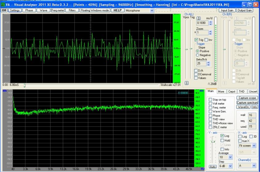
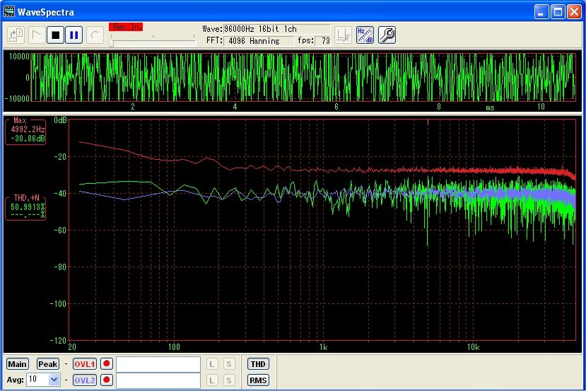
Instead of using real hardware shift registers (e.g. MC4015) a microcontroller can do the job. Just define 6 registers and with the rol command the content is shifted one bit at each clock cycle. An exclusive-OR provides the feedback. The output will look like this
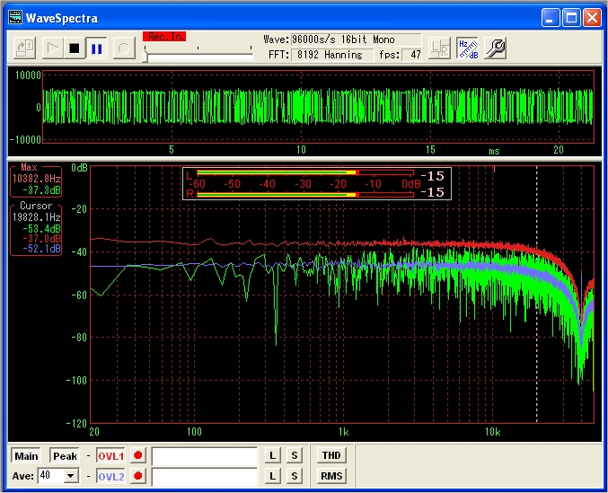
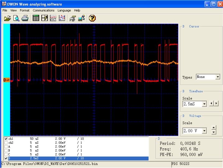
The upper oscilloscope trace shows the pseudorandom bit sequence. Below is the spectrum which is fairly flat below 10 kHz and shows a dip at the clock frequency of 40 kHz. The noise generator's output is normally useful up to 20% of it's clock frequency and would require a simple low pass RC filter. The PC's soundcard sampling frequency is 96000 Hz in this case, so the spectrum's upper frequency limit is 48000 Hz as shown above. This fits quite well with the ATTiny15 clock frequency of 40000 Hz. Of course an ATTiny45 would allow higher clock frequencies
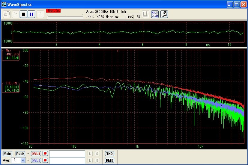
Let's disregard this for a while and see what we can do. Here is a quick test to find the resonance frequency of a parallel LC circuit . Well, it needs the noise generator and a PC with the good Wavespectra software, so much for the equipment. The LC circuit under test is just wired in series between the noise generator and the audio input of the PC.
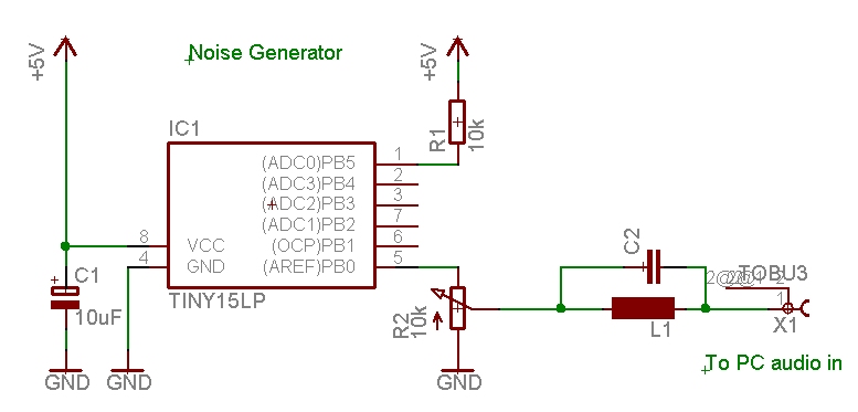
Circuit diagram of the test setup.
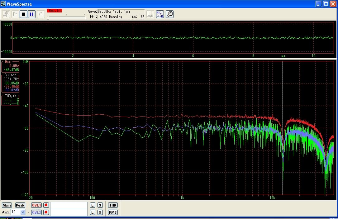
View of a spectrogram of a LC circuit wired in series. The resonance (a dip
in this case) is at 13 kHz. Quick and easy.
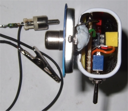
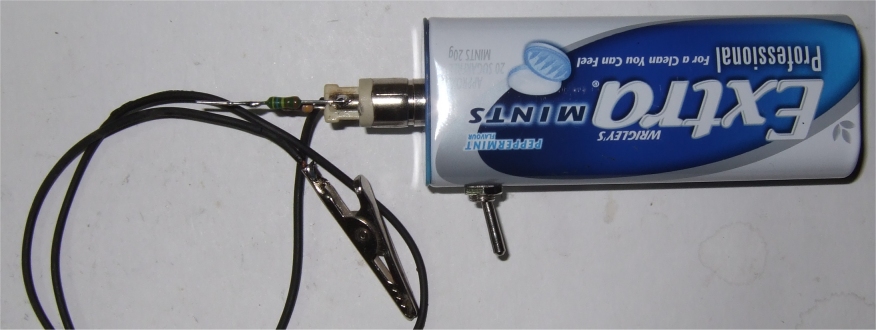
Looks worthwhile to build this noisegenerator. Below is a proposal to put it in a Mints box.
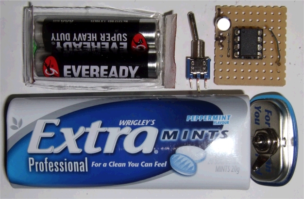
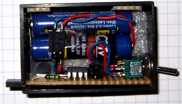
These are the parts needed Then comes the tricky assembly, there is just enough space to get all parts in.
Looks worthwhile to build this noisegenerator. Below is a proposal to put it in a Mints box.
These are the parts needed Then comes the tricky assembly, there is just enough space to get all parts in.
Finally done. On the output is a fixed resistor voltage divider which serves
as a tip to inject the noise.
This 39 bit maximal length noise generator repeats every 549,755,813,887 cycles. With a clock of 40000/sec it takes 13743895.35 seconds, or 3817 hours, or 159 days before the cycle repeats. Gives enough time to complete a measurement.
download NoiseG3.asm
This program is distributed in the hope that it will be useful but WITHOUT ANY WARRANTY;
References
Horowitz & Hill, The Art of Electronics, Cambridge University Press 1980, 1989
David B. VanHorn, dvanhorn@cedar.net
Software for the PC:
Wavespectra software (it's in japanese, so I can't read who programmed it) also recommended: VA -- Visual Analyzer http://www.sillanumsoft.org
Noise-Generator-Anpassung an den Tiny13, Beitrag zum Oster-Contest 2013
Der noise generator geht auch mit dem AT13 mit dem Vorteil einer höheren
Taktfrequenz von 9.6 MHz. Beim AT13 wird die Taktfrequenz per Software
umgeschaltet, so dass man die fuses nicht programmieren muss. Die ISR läuft
jetzt mit 200 kHz und entsprechend flacher ist das Spektrum bis ca. 40 kHz. Mehr
kann die Soundkarte ohnehin nicht.
Das Spektrum bei direkter Verbindung zur Soundkarte, also ziemlich flach bis 40 kHz.
Mit einem einfachen RC Filter mit R 10k und C 100 nF wird das Rauschsignal gefiltert. Die Grenzfrequenz ist bei 1/(2 pi R C) etwa 160 Hz. Im Scope sieht man auch ein relativ flaches Signal in der Mitte, das Spektrum aber hat den RC typischen sanften Abfall zu höheren Frequenzen.
Die
Messung geht sicher schneller als mit einem sweep frequency generator und einem
mV meter.
Download: NoiseG13.zip
;***************************************************************************
;
; ATTiny13  Pseudonoise generator, output on PB0
;
; clock prescaler set by software to 9.6 MHz, 1.042E-07 sec/cycle
; at 9.6 MHz the ISR needs below 3 us to complete, see pulse on PB3
; now reload is set to 5us cycle time or 200 kHz
; there is still some room left (abt 3 us), frequency could be higher
;
; 39 bit maximal length generator. Repeats every 549,755,813,887 cycles
; at 200,000 Hz the repeat is 2.748.779,07 seconds, or
; 763 hours, or 32 days(!)
;
; GS May-2010 - 2013, based on ATtiny15 noiseG3.asm
; original code see eof
;
;  This program is free software; you can redistribute it and/or
;  modify it under the terms of the GNU General Public License.
;  This program is distributed in the hope that it will be useful,
;  but WITHOUT ANY WARRANTY;
;
;***************************************************************************
; The timing is adapted for 9.6 MHz
; clock prescaler set to 0 in reset so we have 9.6 MHz clock
;***************************************************************************
;
;		Pinout ATtiny13/ATtiny13V   8-PDIP/SOIC
;
;(PCINT5/RESET/ADC0/dW)	PB5	VCC
;(PCINT3/CLKI/ADC3) 	PB3	PB2 (SCK/ADC1/T0/PCINT2)
;(PCINT4/ADC2) 		PB4	PB1 (MISO/AIN1/OC0B/INT0/PCINT1)
;			GND	PB0 (MOSI/AIN0/OC0A/PCINT0)
;***************************************************************************
;
; PB4 input  not used
; PB3 output set/reset in ISR
; PB2 output noise inverted
; PB1 output not used
; PB0 output noise
;
;***************************************************************************

.DEVICE ATtiny13	; for gavrasm 3.3
;
;***************************************************************************
;Register Definitions
;***************************************************************************
;
;
.def	STEMP		= R1	;
.def	PN_A		= R2	;7-0
.def	PN_B		= R3	;15-8
.def	PN_C	   	= R4	;23-9
.def	PN_D		= R5	;-24
.def	PN_E		= R6	;
.def	PN_F		= R7	;
.def	PN_G		= R8	;

.def	T0reload	= R15
.def	TEMP		= r16	;
.def	TEMP2		= r17	;
.def	ITEMP		= r18	;
.def	ITEMP2		= r19	;
;
;
;***************************************************************************

.equ	toggle		= PB3
.equ	noiseinv	= PB2
.equ	noiseout	= PB0

.equ	reload		= 256 - 48	; 5 us Timer0

;***************************************************************************
.cseg
.org 0
; ***** INTERRUPT VECTORS **************************************************
	rjmp	reset
	reti 			; INT0addr= 0x0001 External Interrupt 0
	reti	 		; PCI0addr= 0x0002 Pin change Interrupt
	rjmp	TIM0_OVF	; OVF0addr= 0x0003 Timer/Counter0 Overflow
	reti
	reti
	reti
	reti
	reti
;
;***************************************************************************
;
; Timer/Counter0 Overflow Interrupt
;
;***************************************************************************
TIM0_OVF:
		in		STEMP,SREG	; Get Status bits
		sbi		PORTB,toggle	; DEBUG Show we are in the ISR
		out		TCNT0,T0reload	; for 5 us Interrupt


		;Generate the feedback from bits 39,35 (NOTE! Hill uses 1,2,3,4 numbering)
		clr		ITEMP		;
		clr		ITEMP2		;
		sbrc		PN_E,6		;39
		sbr		ITEMP,1<<0	;XXXXXXXA
		sbrc		PN_E,2		;35
		sbr		ITEMP2,1<<0	;XXXXXXXB
		eor		ITEMP2,ITEMP	;Xor
		ror		ITEMP2		;Put bit 0 in carry

		;Shift everyone over, and the carry into the register.
		;104 bits long. If you use maximal length, this will last
		;way longer than the universe.

						;Bits   Hill's bits
		rol		PN_A		;7-0     8-1
		rol		PN_B		;15-8    16-9
		rol 		PN_C		;23-16   and so on
		rol		PN_D		;31-17
		rol		PN_E		;39-32   40-33
		rol		PN_F		;47-40


		;Output the bit
		sbrs	PN_A,1			;
		rjmp	Output_Zero		;

		sbi	PORTB, noiseout		; set
		cbi	PORTB, noiseinv		; clear
		rjmp	TIM0_DONE		;

Output_Zero:
		cbi	PORTB, noiseout		; clear
		sbi	PORTB, noiseinv		; set

TIM0_DONE:
		cbi	PORTB,toggle		;toggle output off
		out	SREG,STEMP		;Put the status bits back
		reti						;
;
;***************************************************************************
reset:
		; writing the calibration byte to the OSCCAL Register.
		;ldi	temp,0x7A    		; config val
		;out	OSCCAL,temp 		; for the cpu clock
		;nop
		;nop

    		ldi    temp,0b11110000
    		out    PORTB,temp
    		ldi    temp,0b00001111
    		out    DDRB,temp

    		ldi    temp,0b10000000		; turn off analog comp.
    		out    ACSR,temp

   		ldi    	temp,0b10000000		; clock prescaler change enable
   		out	CLKPR,temp
    		ldi     temp,0b00000000		; clock prescaler set to 0
   		out	CLKPR,temp
   		nop				; wait a little when switching
   		nop
   		nop
   		nop

; timer0 setup:
		ldi	temp,0b00000010		; Bit 1 – TOIE0: Timer/Counter0 Overflow Interrupt Enable
		out	TIFR0,temp 		; clear pending Interrupt
		out	TIMSK0,temp 		; in the Timer Interupt Mask Register

		ldi	temp,0b00000001 	; Timer/Counter 0 clocked at CK/1
		out	TCCR0B,temp		; 9,6 Mhz
		ldi	temp, reload		; Timer/Counter 0 reload
		out	TCNT0,temp		; for 5 us Interrupt

		mov	T0reload, temp

		ldi	TEMP,$55		; Init the PN generator
		mov	PN_A,TEMP		;
		mov	PN_B,TEMP		;
		mov	PN_C,TEMP		;
		mov	PN_D,TEMP		;
		mov	PN_E,TEMP		;
		mov	PN_F,TEMP		;

		sei				; enable interrupts
Idle:						;
		rjmp	Idle			; That's all we do.
;

;***************************************************************************

;Some other two tap point SR combinations, from Art of Electronics
;Note, hill counts bits as 1,2,3,4, not 0,1,2,3
;Tap points  	 Length
;3,2	              7
;4,3	             15
;5,3	             31
;6,5	             63
;7,6	            127
;9,5	            511
;10,7	          1,023
;11,9	          2,047
;15,14	         32,767
;17,14	        131,071
;18,11	        262,143
;20,17	      1,048,575
;21,19	      2,097,151
;22,21	      4,194,303
;23,18	      8,388,607
;25,22	     33,554,431
;28,25	    268,435,455
;29,27	    536,870,911
;31,28	  2,147,483,647
;33,20	  8,589,934,591
;35,33	 34,359,738,367
;36,25	 68,719,476,735
;39,35	549,755,813,887
;
;A 100 bit register, clocked at 10 mHz would outlast the age
;of the universe, by 1,000,000 times.
;
;***************************************************************************
; Noisy Box     M A I N   M O D U L E
;
; Date				;6/30/04
; Version			:1.00
; Support telephone	:765 287 1989  David B. VanHorn
; Support Email		:dvanhorn@cedar.net
; Target MCU		:Atmel Tiny-11
;
; DESCRIPTION
;
; Pseudonoise generator, output on B0.
;
;***************************************************************************
;***************************************************************************
;
; Atiny15  Pseudonoise generator, output on B0
; ISR fires at 40 kHz @ 1.6 MHz, that's the AT15 limit
; AT45 use a 8 Mhz clock frequency -> 200 kHz ISR
; no matter what, the interrupt needs abt 40 cycles to complete
;
; GS May-2010
; original code see eof
;
;  This program is free software; you can redistribute it and/or
;  modify it under the terms of the GNU General Public License.
;  This program is distributed in the hope that it will be useful,
;  but WITHOUT ANY WARRANTY;
;
;***************************************************************************
; The timing is adapted for 1.6 MHz
; this At15 reads OSCCAL config val=0x7A
;***************************************************************************
;			ATtiny15 dip
;	(RESET/ADC0) 	PB5	VCC
;	(ADC3) 		PB4	PB2 (ADC1/SCK/T0/INT0)
;	(ADC2) 		PB3	PB1 (AIN1/MISO/OC1A)
;			GND	PB0 (AIN0/AREF/MOSI)
;***************************************************************************
;
; PB4 input  not used
; PB3 output set/reset in ISR
; PB2 output noise inverted
; PB1 output toggle OC1A
; PB0 output noise
;
;***************************************************************************

.DEVICE ATtiny15	;for gavrasm
;
;***************************************************************************
;Register Definitions
;***************************************************************************
;
;
.def	STEMP		= R1	;
.def	PN_A		= R2	;7-0
.def	PN_B		= R3	;15-8
.def	PN_C	   	= R4	;23-9
.def	PN_D		= R5	;-24
.def	PN_E		= R6	;
.def	PN_F		= R7	;
.def	PN_G		= R8	;

.def	TEMP		= R16	;
.def	TEMP2		= R17	;
.def	ITEMP		= R18	;
.def	ITEMP2		= R19	;
;
;
;***************************************************************************

.equ	toggle		= PB3
.equ	noiseinv	= PB2
.equ	noiseout	= PB0

.equ	topcount	= 40-1	; 40 kHz @ 1.6 MHz

;***************************************************************************
.cseg
.org 0
; ***** INTERRUPT VECTORS **************************************************
	rjmp	reset		; Reset-vector address 0000
	reti			; INT0addr= 0x0001	External Interrupt 0
	reti 			; PCI0addr= 0x0002  	Pin Interrupt Request
	rjmp	TIM1_cmp 	; OC1addr = 0x0003 	Timer/Counter1 Compare Match
	reti 			; OVF1addr= 0x0004	Timer/Counter1 Overflow
	reti			; OVF0addr= 0x0005	Timer/Counter0 Overflow
	reti 			; ERDYaddr= 0x0006	EEPROM Ready
	reti 			; ACIaddr = 0x0007 	Analog Comparator
	reti 			; ADCCaddr= 0x0008  	ADC Conversion Ready
;;
;***************************************************************************
;
;Timer Tick 40kHz
;
TIM1_cmp:
		in		STEMP,SREG	;Get Status bits
		sbi		PORTB,toggle	;DEBUG Show we are in the ISR

;***************************************************************************
;39 bit maximal length generator. Repeats every 549,755,813,887 cycles
;40,000 clk/sec, so the repeat is 13743895.35 seconds, or
;3817 hours, or 159 days(!)

		;Generate the feedback from bits 39,35 (NOTE! Hill uses 1,2,3,4 numbering)
		clr		ITEMP		;
		clr		ITEMP2		;
		sbrc		PN_E,6		;39
		sbr		ITEMP,1<<0	;XXXXXXXA
		sbrc		PN_E,2		;35
		sbr		ITEMP2,1<<0	;XXXXXXXB
		eor		ITEMP2,ITEMP	;Xor
		ror		ITEMP2		;Put bit 0 in carry

		;Shift everyone over, and the carry into the register.
		;104 bits long. If you use maximal length, this will last
		;way longer than the universe.

						;Bits   Hill's bits
		rol		PN_A		;7-0     8-1
		rol		PN_B		;15-8    16-9
		rol 		PN_C		;23-16   and so on
		rol		PN_D		;31-17
		rol		PN_E		;39-32   40-33
		rol		PN_F		;47-40


		;Output the bit
		sbrs	PN_A,1			;
		rjmp	Output_Zero		;

		sbi	PORTB, noiseout		; set
		cbi	PORTB, noiseinv		; clear
		rjmp	TIM1_DONE		;

Output_Zero:
		cbi	PORTB, noiseout		; clear
		sbi	PORTB, noiseinv		; set

TIM1_DONE:
		cbi	PORTB,toggle		;toggle output off
		out	SREG,STEMP		;Put the status bits back
		reti						;
;
;***************************************************************************
reset:
		; writing the calibration byte to the OSCCAL Register.
		ldi	temp,0x7A    		; config val
		out	OSCCAL,temp 		; for the cpu clock
		nop
		nop

    		ldi    temp,0b11110000
    		out    PORTB,temp
    		ldi    temp,0b00001111
    		out    DDRB,temp

    		ldi    temp,0b10000000		;turn off analog comp.
    		out    ACSR,temp
						; timer setup:
		ldi	TEMP,$55		; Init the PN generator
		mov	PN_A,TEMP		;
		mov	PN_B,TEMP		;
		mov	PN_C,TEMP		;
		mov	PN_D,TEMP		;
		mov	PN_E,TEMP		;
		mov	PN_F,TEMP		;

		ldi	temp, topcount		; Timer/Counter 1 top count
		out	OCR1A,temp		; compare value
		ldi	temp, 0b10010101	; Timer/Counter 1 ctc, toggle OC1A, use sysCK
		out	TCCR1,temp		;
    		ldi	temp, 0b01000000	; enable OCIE1A interrupt
    		out	TIMSK,temp


		sei				; enable interrupts
Idle:						;
		rjmp	Idle			; That's all we do.
;

;***************************************************************************

;Some other two tap point SR combinations, from Art of Electronics
;Note, hill counts bits as 1,2,3,4, not 0,1,2,3
;Tap points  	 Length
;3,2	              7
;4,3	             15
;5,3	             31
;6,5	             63
;7,6	            127
;9,5	            511
;10,7	          1,023
;11,9	          2,047
;15,14	         32,767
;17,14	        131,071
;18,11	        262,143
;20,17	      1,048,575
;21,19	      2,097,151
;22,21	      4,194,303
;23,18	      8,388,607
;25,22	     33,554,431
;28,25	    268,435,455
;29,27	    536,870,911
;31,28	  2,147,483,647
;33,20	  8,589,934,591
;35,33	 34,359,738,367
;36,25	 68,719,476,735
;39,35	549,755,813,887
;
;A 100 bit register, clocked at 10 mHz would outlast the age
;of the universe, by 1,000,000 times.
;
;***************************************************************************
; Noisy Box     M A I N   M O D U L E
;
; Date				;6/30/04
; Version			:1.00
; Support telephone	:765 287 1989  David B. VanHorn
; Support Email		:dvanhorn@cedar.net
; Target MCU		:Atmel Tiny-11
;
; DESCRIPTION
;
; Pseudonoise generator, output on B0.
;
;***************************************************************************