
GSFD = greatly simplified frequency detection
The standard way to analyze frequencies is to use the Fast Fourier Transform (FFT) algorithm. There are implementations available which will run on a microcontroller but all require lookup tables and butterfly shuffling of data and take time to compute. Furthermore the frequency resolution is limited on a microcontroller, the binsize is sampling frequency / number of samples and that may be too coarse for some applications. For single frequency detection DFT's (discrete fourier transforms) are usually choosen, where
DFT(x) = sum( x(k) * W(k) ) k=1,..,N
where x(k) are the incoming time samples and W(k) is the kernal function
W(k) = e^(j*2*pi*f*k/N)
W(k) = cos(2*pi*f*k/N) + j*sin(2*pi*f*k/N)
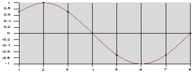
Multiply the samples by sine waves and cosine waves and add them, then the
magnitude of these (complex) numbers will show how much energy is present for
the frequency of the input signal.
How to make it simple
The target here is to detect a single frequency in a sampled waveform x(k) using simple algorithms without lookup tables or ram storage.
In order to simplify computation it is desirable that the sampled waveform fits into one byte. This can be achieved by sampling the incoming signal at 8 times the target frequency.
In addition, a one bit A/D converter is used for sampling, basically one input of the microcontroller is a comparator. These two steps make further computation easier and of course faster. The one bit A/D conversion allows to use microcontrollers which have no built in A/D converter, like the ATiny2313.
GSFD by correlation :
In order to detect a target waveform contained in the incoming signal, multiply the two and add the resulting product. The single number that results from this procedure is a measure of how similar the two signals are.
*1)
Each sample in the frequency domain is found by multiplying the time domain signal by the sine or cosine wave being looked for, and adding the resulting points. It means correlating the input signal with each basis function. Now with a 1 bit A/D converter and each time domain signal in 1 byte the sin term is also 1 byte: sin term = 11110000 and the cos term 00111100, which is fixed at the given frequency. For multiplication an exclusive OR operation (eor) is used.
*2) If we were computing DFT's with sine and cosines, then the signal strength of a particular frequency is easily ascertained by finding the familiar magnitude:
strength ~ sqrt( real(DFT)^2 + imaginary(DFT)^2)
In other words, the result of a DFT is a complex number when the complex kernal is used. And the magnitude of a complex number is the square root of the sum of the real part squared plus the imaginary part squared. This is a cumbersome operation. The square root of the sum of the squares normalization is called the "square norm". It is a subset of the general class of normed linear spaces called the "p-norm". In this case, the linear space consists of two components: the real and imaginary parts of the DFT. The p-norm is:
strength ~ (abs(real(DFT))^p + abs(imaginary(DFT))^p) ^ 1/p
And this is the same as the square norm when p is 2. Now if p is 1 we up end
with an extremely simple formula, the 1-norm:
strength ~ abs(real(DFT)) + abs(imaginary(DFT))
So, strength is something like sum( f1* sin )+sum( f1* cos ), and remember f1
* sin is minimum with good correlation because eor 1, 1 = 0
The sin term = 11110000 , cos term 00111100 and incoming wave may be 11110000.
In assembly this is
eor inbyte, Wcos ; multiply inbyte and f2 cos byte (in situ)
add AcosL, inbyte ; and add to accu
adc AcosH, zero ; sum (f1 * cos)
and the same for the sin term. After sampling e.g. 64 samples add the sin and cos term and that gives the signal strength.
GSFD with Goertzel algorithm
The Goertzel algorithm computes a sequence, s(n), given an input sequence, x(n):
s(n) = x(n) + 2cos(2*pi*omega)s(n - 1) - s(n - 2)
where s( - 2) = s( - 1) = 0 and omega is the frequency of interest, in cycles per sample. This effectively implements a second-order IIR filter. *3)
The normal Goertzel algorithm is computed as follows:
k:= Trunc((N_samples*Ftarget/Fsample)+0.5);
omega := 2.0 * pi * k / N_samples;
sine := sin(omega); cosine := cos(omega);
coeff := 2 * cosine;
N_samples are the number of samples, e.g. 64.
then in the sampling loop:
Q0 := coeff * Q1 - Q2 + x(n);
Q2 := Q1;
Q1 := Q0;
With the sampling frequency 8 * frequency of interest follows k = N_samples/8
-> omega = 2*pi/8 = 0.785 -> cos(omega)=0.707
with N_samples beiing an integer multiple of 8 then sin(omega) = cos(omega)
= 0.707 and coeff = 1.41
As second step a fairly crude assumption is made: now a simplified coeff is set: cos(omega) = 1, coeff = 2. The values are off by 30% but the relation is still the same, a factor of 2. In assembly this is implemented quite easily:
; GSFD Goertzel test
mov Q0L, Q1L ;
mov Q0H, Q1H ; Q0 = Q1
lsl Q0L
rol Q0H ; Q0 = 2 * Q1
add Q0L, inbyte
adc Q0H, zero ; Q0 = 2 * Q1 + f1_in
sub Q0L, Q2L
sbc Q0H, Q2H ; Q0 = 2 * Q1 + f1_in - Q2
mov Q2L, Q1L
mov Q2H, Q1H ; Q2 = Q1
mov Q1L, Q0L
mov Q1H, Q0H ; Q1 = Q0
The signal strength can be computed using the same cosine term required to compute s as
X(omega)X'(omega) = s(N - 2)^2 + s(N - 1)^2 - 2cos(2*pi*omega)s(N - 2)s(N - 1)
which is currently not implemented, seems enough to use the Q0 term.
Experimental results
To test the above algorithms a ATiny2313 clocked by a 10 MHz quartz was programmed in assembly language. Our frequency of interest is 1 kHz so the sampling frequency is set to 8 kHz and 64 samples are taken, 8 ms for the whole process. At the start we synchronize sampling with f1_in: wait for a low on the input pin then a high, then start sampling. After 64 samples the data are converted to decimal values and send through serial interface to a PC for recording.
The incoming waveform is a sine wave, generated by a programmable and quartz controlled function generator, a MiniDDS in this case. The incoming frequency covers a range from 940 to 1250 Hz in 10 Hz steps, below are the results
| F[Hz] | Goe | Q0 | Q1 | Q2 | Sq | F[Hz] | Corr | Sin | Cos | Sum |
| 900 | G | 3360 | 3360 | 2614 | 4257,1 | 900 | S | 1082 | 726 | 1808 |
| 940 | G | 3257 | 3257 | 2662 | 4206,5 | 940 | S | 1251 | 351 | 1602 |
| 950 | G | 3656 | 3656 | 2900 | 4666,5 | 950 | S | 1138 | 366 | 1504 |
| 960 | G | 3656 | 3656 | 2950 | 4697,7 | 960 | S | 1138 | 366 | 1504 |
| 970 | G | 4088 | 4088 | 3236 | 5213,8 | 970 | S | 964 | 464 | 1428 |
| 980 | G | 4260 | 4260 | 3288 | 5381,3 | 980 | S | 828 | 600 | 1428 |
| 990 | G | 5024 | 5024 | 3928 | 6377,3 | 990 | S | 696 | 732 | 1428 |
| 1000 | G | 6944 | 6944 | 5208 | 8680,0 | 1000 | S | 56 | 1372 | 1428 |
| 1010 | G | 6824 | 6824 | 5128 | 8536,0 | 1010 | S | 16 | 1412 | 1428 |
| 1020 | G | 6777 | 6777 | 5088 | 8474,4 | 1020 | S | 9 | 1421 | 1430 |
| 1030 | G | 6686 | 6686 | 5043 | 8374,6 | 1030 | S | 59 | 1471 | 1530 |
| 1040 | G | 6572 | 6572 | 4950 | 8227,6 | 1040 | S | 70 | 1498 | 1568 |
| 1050 | G | 6555 | 6555 | 4960 | 8220,1 | 1050 | S | 107 | 1535 | 1642 |
| 1060 | G | 6415 | 6415 | 4864 | 8050,5 | 1060 | S | 159 | 1579 | 1738 |
| 1070 | G | 6277 | 6277 | 4815 | 7911,1 | 1070 | S | 262 | 1546 | 1808 |
| 1080 | G | 6157 | 6157 | 4751 | 7776,9 | 1080 | S | 334 | 1474 | 1808 |
| 1090 | G | 5939 | 5939 | 4679 | 7560,7 | 1090 | S | 508 | 1368 | 1876 |
| 1100 | G | 5666 | 5666 | 4471 | 7217,6 | 1100 | S | 571 | 1303 | 1874 |
| 1110 | G | 5448 | 5448 | 4370 | 6984,1 | 1110 | S | 710 | 1162 | 1872 |
| 1120 | G | 5350 | 5350 | 4258 | 6837,6 | 1120 | S | 692 | 1144 | 1836 |
| 1130 | G | 4707 | 4707 | 3808 | 6054,5 | 1130 | S | 883 | 951 | 1834 |
| 1140 | G | 4807 | 4807 | 3872 | 6172,5 | 1140 | S | 855 | 915 | 1770 |
| 1150 | G | 4946 | 4946 | 3926 | 6314,8 | 1150 | S | 780 | 960 | 1740 |
| 1160 | G | 4930 | 4930 | 3922 | 6299,8 | 1160 | S | 768 | 972 | 1740 |
| 1170 | G | 5049 | 5049 | 3915 | 6389,0 | 1170 | S | 638 | 1098 | 1736 |
| 1180 | G | 4425 | 4425 | 3403 | 5582,2 | 1180 | S | 750 | 954 | 1704 |
| 1190 | G | 4475 | 4475 | 3443 | 5646,2 | 1190 | S | 728 | 948 | 1676 |
| 1200 | G | 4761 | 4761 | 3596 | 5966,4 | 1200 | S | 605 | 1073 | 1678 |
| 1210 | G | 4725 | 4725 | 3590 | 5934,1 | 1210 | S | 655 | 1115 | 1770 |
| 1220 | G | 4692 | 4692 | 3540 | 5877,6 | 1220 | S | 624 | 1212 | 1836 |
| 1230 | G | 4764 | 4764 | 3640 | 5995,4 | 1230 | S | 660 | 1112 | 1772 |
| 1240 | G | 4766 | 4766 | 3642 | 5998,2 | 1240 | S | 660 | 1112 | 1772 |
| 1250 | G | 5078 | 5078 | 3858 | 6377,3 | 1250 | S | 564 | 1272 | 1836 |
| 1300 | G | 4410 | 4410 | 3432 | 5588,1 | 1300 | S | 802 | 998 | 1800 |
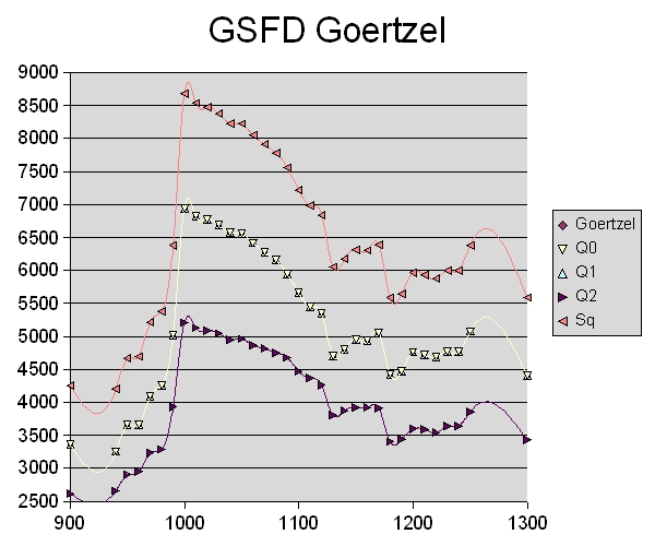
result of GSFD with Goertzel algorithm
We see that the Goertzel Q0 has a maximum at 1 kHz, falling sharply at the lower frequency side and sloping gently at higher frequencies. Q0 and Q1 are the same, Sq is sqrt(Q0^2 + Q2^2) plotted to see if it might be useful but it seems enough to use Q0 and a threshold to detect the incoming frequency. The detection range can be broad or narrow, depending on the threshold.
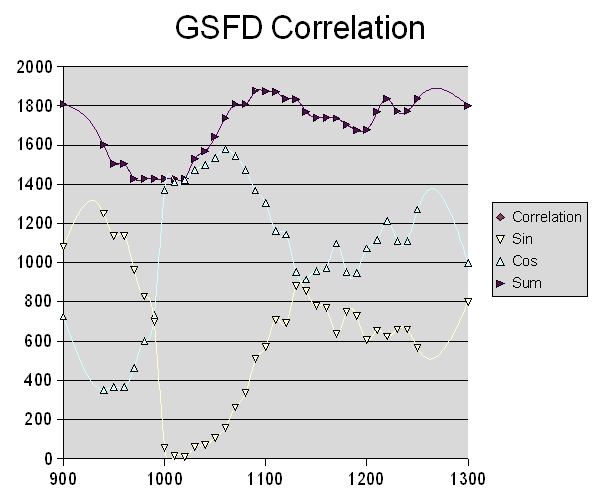
result of GSFD by correlation :
At 1 kHz the sine term of the correlation has low values as expected when using an exclusive OR operation (eor) for multiplication, the absolute minimum is at 1020 Hz. Same as before the sine is falling sharply at the lower frequency side and sloping gently at higher frequencies. The sum of sine and cos term gives a detection range of 60 Hz centered around 1 kHz. It is probably enough to use the sine term and a threshold to determine the filter bandwidth.
How sensitive are both algorithms on harmonics of the frequency of interest (1 kHz)? Here are the results:
| F[Hz] | Goe | Q0 | Q1 | Q2 | Sq | F[Hz] | Corr | Sin | Cos | Sum |
| 500 | G | 5616 | 5616 | 421 | 5631,8 | 500 | S | 396 | 1344 | 1740 |
| 1500 | G | 5504 | 5504 | 4128 | 6880,0 | 1500 | S | 400 | 1372 | 1772 |
| 1990 | G | 5264 | 5264 | 4150 | 6703,1 | 1990 | S | 682 | 998 | 1680 |
| 2000 | G | 6664 | 6664 | 4998 | 8330,0 | 2000 | S | 210 | 1470 | 1680 |
| 2010 | G | 5950 | 5950 | 4488 | 7452,8 | 2010 | S | 390 | 1650 | 2040 |
Both are not much affected by odd harmonics but the GSFD Goertzel algorithm has another maximum at 2 kHz ,6664, lower than the one at 1 kHz, 6944, but still visible and quite close. The GSFD correlation algorithm also reacts, the sum term goes from 1428 to 1680 but this is about 15 % higher and it seems more resistant to harmonics. If the input is open and 50 Hz get in the microcontroller the Goertzel is at 7000 and fires whereas the correlation does not.
Conclusion
It is possible to detect a single frequency in a sampled waveform x(k) using simple algorithms without lookup tables or ram storage, provided:
a) a one bit A/D converter is used for sampling
b) the incoming signal is sampled at 8 times the frequency of interest therefore
fits into one byte
Both algorithms can run on a basic microcontroller and will detect the frequency of interest quite well. The correlation algorithm however is easier to program and sensitive and the result will be as good as the threshold setting.
Here sampling is synchronized with the incoming waveform, we wait for a low on the input pin then a high and then start sampling. It would be interesting to see what happens if this is not done and the phase is more or less random. The incoming waveform was a clean sine signal, so it remains to be tested in real world noisy signals.
In a more practical application it can be used for DTMF decoding which has not been tested yet. After sampling 64 samples the sampling frequency is changed, 8 times for the 8 DTMF frequencies, e.g. 1209 Hz would be sampled with 9672 Hz. The process takes about 64 ms to complete.
Anyway, a LM567 is the easiest way to detect a single frequency but this is more fun.
references:
*1) :The Scientist and Engineer's Guide to Digital Signal Processing By Steven
W. Smith, Ph.D.
*2) Scott Dattalo : scott@dattalo.com. DTMF - Decoding with a 1-bit A/D converter
*3) Wikipedia, Goertzel algorithm
;***************************************************************************
; GSFD = greatly simplified frequency detection
;
; ATiny2313  GSFD Goertzel test & GSFD correlation test (2 in 1)
;
; for this test the target frequency is 1 kHz,
; sampling frequency 8 * target = 8kHz, 1 bit sampling of f1
;
; first step: sampling frequency = 8 * target frequency therefore sampled f1 fit into 1 byte
; this greatly simplifies the calculations for the Goertzel algorithm, no table needed
;
; normal Goertzel algorithm:
;		k:= Trunc((N_samples*Ftarget/Fsample)+0.5);
;		omega := 2.0 * pi * k / N_samples;
;		sine := sin(omega); cosine := cos(omega);
;		coeff := 2 * cosine;
;
; then in the sampling loop:
;               Q0 := coeff * Q1 - Q2 + f1;
;               Q2 := Q1;
;               Q1 := Q0;
;
; with sampling frequency 8 * target follows  k = N_samples/8 -> omega = 2*pi/8 = 0.785 -> cos(omega)=0.707
; with N_samples x * 8, sin(omega) = cos(omega) = 0.707 and coeff = 1.41
; second step: now simplified coeff is set: cos(omega) = 1, coeff = 2
;
; magnitude is something like the Q0 term
;
; GSFD correlation test:
;
; f1 is sampled at 8 * target frequency
; therefore sampled f1 and fixed f2 fit into 1 byte
; this greatly simplifies multiplication (eor) and the frequency detection by correlation
; f1 is sampled, f2 sin term 11110000, cos term 00111100
; frequency detection by correlation of f1 with f2
; magnitude is something like sum( f1* sin )+sum( f1* cos )
; f1 * sin is zero with good correlation, eor 1, 1 = 0
;
; 10MHz quartz osc
; GS June 2010
;
;***************************************************************************
;                 ATiny2313  PDIP
;
; (RESET/dW) 	  PA2 1   20 VCC
; (RXD) 	  PD0 2   19 PB7 (UCSK/SCK/PCINT7)
; (TXD) 	  PD1 3   18 PB6 (MISO/DO/PCINT6)
; (XTAL2) 	  PA1 4   17 PB5 (MOSI/DI/SDA/PCINT5)
; (XTAL1) 	  PA0 5   16 PB4 (OC1B/PCINT4)
; (CKOUT/XCK/INT0)PD2 6   15 PB3 (OC1A/PCINT3)
; (INT1) 	  PD3 7   14 PB2 (OC0A/PCINT2)
; (T0) 		  PD4 8   13 PB1 (AIN1/PCINT1)
; (OC0B/T1) 	  PD5 9   12 PB0 (AIN0/PCINT0)
;		  GND 10  11 PD6 (ICP)
;***************************************************************************

.DEVICE ATtiny2313		;for gavrasm

.equ 		clock 		= 10000000

; more Definitions
.equ 		baudrate 	= 9600
.equ 		baudval 	= clock/(16*baudrate)-1
.equ 		c_value		= 1250-1	; Compare value for compare interrupt T1
						; 1250 cycles@10Mhz = 8 kHz
.equ		N_samples	= 64		; number of samples

.equ		sinterm		= 0b11110000	; fixed when sampling f = 8 * target f
.equ		costerm		= 0b00111100

.equ		gthresh		= 6000		; Goertzel
.equ		csinthresh	= 60		; sin part of correlation

.equ 		c1s		= 100 		; Wait  (100 * 5 ms)
.equ 		c5ms		= clock/800 	; 5 ms Wait

.equ		toggle		= PIND6		; timer1
.equ		f1_in		= PINB0
.equ		fout		= PINB1
;				PB2 		(OC0A toggle)
.equ		c_ok		= PINB3
.equ		c_ok1		= PINB4
.equ		g_ok		= PINB5

; r0 used
.def Zero	= r1            ;
.def IntrSREG	= r2            ;
.def inbyte	= r3
.def Wsin	= r4		; sin wave f2
.def Wcos	= r5

.def Q0L	= r6		; Q0, each 2 byte
.def Q0H	= r7		;
.def Q1L	= r8		; Q1
.def Q1H	= r9		;
.def Q2L	= r10		; Q2
.def Q2H	= r11		;
.def AsinL	= r12		; sum( sin * f_in)
.def AsinH	= r13
.def AcosL	= r14		; sum( cos * f_in)
.def AcosH	= r15

.def Temp0      = r16             ;
.def Temp1      = r17             ;
.def Arg0	= r22             ; Arg0
.def Arg1	= r23             ; Arg1
.def flag	= r24
.def itemp1     = r25             ;
.def icountN8   = r26             ; 8 bit counter
.def icountN    = r27             ; N_samples counter
.def Wsincnt	= r28		; sin wave high value counter

; Z used

;******************************************************************************
; start of code
;******************************************************************************

.cseg
.org 0
		rjmp	RESET

.org 0x04					;0x0004 TIMER1 COMPA Timer/Counter1 Compare Match A
		rjmp	T1_COMPA
.org 0x07
		rjmp	RX_COMPLETE_INT		;0x0007 USART0 RX Complete Interrupt
.org 0x0d
		rjmp	T0_COMPA		;0x000D TIMER0 COMPA Timer/Counter0 Compare Match A

;************************************************************************=
;*
;* T0_COMPA	- Timer0 compare A interrupt routine 10 kHz @ 4 MHz
;*			toggles OC0A on PB2 = 5 kHz
;************************************************************************=


T0_COMPA:	in	IntrSREG, SREG		;


T0_COMPAex:
		out	SREG,IntrSREG
		reti


;************************************************************************=
;*
;* T1_COMPA	- Timer1 compare A interrupt routine 8kHz @ 10 MHz
;*
;************************************************************************=


T1_COMPA:	in	IntrSREG, SREG		;

		sbis	PIND, toggle		; skip if set, toggle pin
		sbi	PORTD, toggle		; else set pin
		sbic	PIND, toggle	 	; skip if clear
		cbi	PORTD, toggle		; else clear pin

		dec	icountN			; get 64 samples
		brne	T1_COMPA0
		ldi	icountN, N_samples	; 64 samples
		sbr	flag, 0b00000001	; set ready flag
		rjmp	T1_COMPAex
T1_COMPA0:
		clc				; sample f1 = f1_in
		sbic	PINB, f1_in	 	; skip if clear
		sec				; if hi set carry
		rol	inbyte			; rol carry in lsb

		dec	icountN8
		brne	T1_COMPAex		; got 1 byte
		ldi	icountN8, 8		; 8 bits

		;add	dcL, inbyte		; DC term
		;adc	dcH, zero

; GSFD Goertzel test
		mov	Q0L, Q1L		;
		mov	Q0H, Q1H		; Q0 = Q1

		lsl	Q0L
		rol	Q0H			; Q0 = 2 * Q1

		add	Q0L, inbyte
		adc	Q0H, zero		; Q0 = 2 * Q1 + f1_in

		sub	Q0L, Q2L
		sbc	Q0H, Q2H		; Q0 = 2 * Q1 + f1_in - Q2

		mov	Q2L, Q1L
		mov	Q2H, Q1H		; Q2 = Q1

		mov	Q1L, Q0L
		mov	Q1H, Q0H		; Q1 = Q0

; GSFD correlation test
		mov	itemp1, inbyte 		; f1 in inbyte
		eor	itemp1, Wsin		; multiply inbyte and f2 sin byte (in situ)
		cpi	itemp1, 90		; some thresh value
		brsh	T1_COMPAa
		inc	Wsincnt			; inc when correlation is high, eor is zero
T1_COMPAa:
		add	AsinL, itemp1		; and add to accu
		adc	AsinH, zero		; sum (f1 * sin)

		eor	inbyte, Wcos		; multiply inbyte and f2 cos byte (in situ)
		add	AcosL, inbyte		; and add to accu
		adc	AcosH, zero		; sum (f1 * cos)


		clr	inbyte			; clear for next sample

T1_COMPAex:
		out	SREG,IntrSREG
		reti

;**********************************************************************
; Interrupt routine for incoming bytes on the RS232 link
;**********************************************************************

RX_COMPLETE_INT:
		cli				; no interrupts now
		in	IntrSREG, SREG		;
		push	temp0
		in 	temp0,UDR
		cpi		temp0,'t'		;
		brne	rx_2
		rjmp	rx_exit
rx_2:
		cpi		temp0,'r'		;
		brne	rx_3
		ldi 	temp0,'H'
		rcall	send_char
		rcall	SendAscii

		ldi 	temp0,'L'
		rcall	send_char
		rcall	SendAscii
		rjmp	rx_exit
rx_3:
		cpi		temp0,'L'		;
		brne	rx_4
		rjmp	rx_exit
rx_4:
		cpi		temp0,'H'		;
		brne	rx_5
		rjmp	rx_exit
rx_5:
		cpi		temp0,'c'		;
		brne	rx_6
rx_51:
		ldi 	temp0,'C'
		rcall	send_char
		rcall	Send1Hex
		rjmp	rx_exit
rx_6:
		cpi		temp0,'d'		;
		brne	rx_7
		rjmp	rx_51
rx_7:
		ldi	temp0,'?'		;something else ???
		rcall	send_char

; always reply with the current
rx_exit:
		;rcall	send_data
		pop	temp0
		out	SREG,IntrSREG
		sei
		reti

;**********************************************************************
; communication functionality
;**********************************************************************
;
; get char in temp0
;
get_char:				; UCSRA: RXC TXC UDRE FE DOR UPE U2X MPCM
	        sbis    UCSRA,RXC      	;wait for a character
	        rjmp    get_char
	        in      temp0,UDR      	;read value
	        ret

; send char in temp0
;
send_char:
	 	sbis 	UCSRA, UDRE	; wait for UDR
	 	rjmp 	send_char
		out	UDR,temp0	; send char in rxtxbyte
		ret			; and return


;* Convert the LSB nibble of temp0 to an ASCII Hex
Send1Asc:
	        cbr    temp0,$F0	; clear upper nibble
	        cpi    temp0,$0A
	        brmi   Send1Asc1
	        subi    temp0, -7	; add 7 for A..F
Send1Asc1:
	        ori    temp0,$30 	; convert to ASCII
	        rcall	send_char
	        ret

;* sends temp0 as ASCII Hex
SendHext0:
	        push	temp0
	        lsr    temp0
	        lsr    temp0
	        lsr    temp0
	        lsr    temp0		; /16
	        rcall  Send1Asc		; send MSB nibble
	        pop	temp0
	        rcall  Send1Asc		; send LSB nibble
	        ret

;* sends Packed BCD in temp0 as ASCII
SendPBCD0:
	        push	temp0
	        swap	temp0
	        rcall   Send1Asc		; send MSB nibble
	        pop	temp0
	        rcall   Send1Asc		; send LSB nibble
	        ret

;***************************************************************************
; Send value in Arg1:Arg0 as Hex ASCII  '=xxxxCRLF' , 7 bytes
; e.g. =0000<CRLF>  to =FFFF<CRLF>
;***************************************************************************

SendAscii:
		ldi	temp0,'='	;start terminal with =
		rcall	send_char
SendAscii1:
		mov	temp1, Arg1	; temp1: input for Bin1ToHex2 Arg1
		swap temp1		; hi byte Arg1
		andi temp1,$0F 		; mask upper nibble
		subi temp1,-'0' 	; add 0 to convert to ASCII
		cpi temp1,'9'+1 	; A..F?
		brcs SendToHex1a1
		subi temp1,-7 		; add 7 for A..F
SendToHex1a1:
		mov	temp0, temp1	;high Ascii
		rcall	send_char

		mov	temp1, Arg1	; temp1: input for Bin1ToHex2
		andi temp1,$0F 		; mask upper nibble
		subi temp1,-'0' 	; add 0 to convert to ASCII
		cpi temp1,'9'+1 	; A..F?
		brcs SendToHex1a0
		subi temp1,-7 		; add 7 for A..F
SendToHex1a0:
		mov	temp0, temp1	;lo LSB Ascii Arg1
		rcall	send_char

Send1Hex:	mov	temp1, Arg0	; temp1: input for Bin1ToHex2 Arg0
		swap temp1 		; upper to lower nibble
		andi temp1,$0F 		; mask upper nibble
		subi temp1,-'0' 	; add 0 to convert to ASCII
		cpi temp1,'9'+1 	; A..F?
		brcs SendToHex1b1
		subi temp1,-7 		; add 7 for A..F
SendToHex1b1:
		mov	temp0, temp1	;lo MSB Ascii
		rcall	send_char

		mov	temp1, Arg0	; temp1: input for Bin1ToHex2
		andi temp1,$0F 		; mask upper nibble
		subi temp1,-'0' 	; add 0 to convert to ASCII
		cpi temp1,'9'+1 	; A..F?
		brcs SendToHex1b0
		subi temp1,-7 		; add 7 for A..F
SendToHex1b0:
		mov	temp0, temp1	;lo LSB Ascii Arg0
		rcall	send_char

SendCrLf:	ldi	temp0,13	;CR terminal end char
		rcall	send_char
		ldi	temp0,10	;LF terminal end char
		rcall	send_char
		ret

;********************************************************************

;******************************************************************************
; reset code
;******************************************************************************

RESET:
		ldi	temp0, RAMEND
		out	SPL, temp0		; setup stack pointer
;		ldi	temp0, 0x5E		; 4.1 k
;		ldi	temp0, 0x5B		; 3.9 kHz
;		ldi	temp0, 0x5D		; ok
;		out	OSCCAL, temp0		; cal, goes up with VCC
		nop
		nop

;************** Ports *****************************************************
		; Port B
		ldi	temp0,0b11111100 	; set pullup and pins
		out	PORTB,	temp0		; 1 = pull-up , 0 = float
		ldi	temp0,0b11111110 	; 1 = output , 0 = input
		out	DDRB,temp0       	; to data direction register

		; Port D
		ldi	temp0,0b00011011 	; set pullups and pins
		out	PORTD,	temp0		; 1 = pull-up , 0 = float
		ldi	temp0,0b01111110 	; Rx input PD0 Tx output PD1
		out	DDRD,temp0       	; to data direction register D

;************** uart ******************************************************
		ldi	temp0,low(baudval)	; UBRRL set uart speed
		out	UBRRL,temp0
		ldi	temp0,high(baudval)	; UBRRL set uart speed
		out	UBRRH,temp0
						; 98 = 10011000
		ldi	temp0,0b10011000	; enable RXint and enable tx/rx
		out	UCSRB,temp0		; UCSRB: RXCIE TXCIE UDRIE RXEN TXEN UCSZ2 RXB8 TXB8

;************** timer1 ***************************************************

		ldi 	temp0,high(c_value)	; Load compare high value
		out	OCR1AH,temp0
		ldi 	temp0,low(c_value)	; Load compare low value
		out	OCR1AL,temp0		; timing @ 10 MHz

		ldi 	temp0,0x00
		out 	TCCR1A,temp0		;Clear timer control reg A
		ldi 	temp0,0b00001001	;CTC
		out 	TCCR1B,temp0		;Clear timer on compare match,CK/1

;************** timer0 ***************************************************

		ldi 	temp0,49		;8 * 50 = 400  -> 10 kHz @ 4MHz
		out 	OCR0A,temp0		;Clear timer on compare match

		ldi 	temp0,0b01000010	;CTC & toggle OC0A
		out 	TCCR0A,temp0		;
		ldi 	temp0,0b00000010	;
		out 	TCCR0B,temp0		;CK/8

		ldi 	temp0,0x41		;TOV1 OCF1A OCF1B – ICF1 OCF0B TOV0 OCF0A: TIFR
		out	TIFR,temp0		;Clear pending timer interrupt
		out	TIMSK,temp0		;Enable Timer 1 and Timer 0 compare interrupt
						;TOIE1 OCIE1A OCIE1B – ICIE1 OCIE0B TOIE0 OCIE0A: TIMSK

;************** misc *****************************************************
		ldi	temp0,(1<<ACD)		; turn off the analog comparator
		out	ACSR,temp0		; to minimize current draw

		sei				;Enble global interrupt

;************** main *****************************************************

		ldi	icountN, N_samples	; 64 samples
		ldi	icountN8, 8		; 8 bit
		ldi 	temp0,sinterm		; sin wave
		mov	Wsin, temp0
		ldi 	temp0,costerm		; cos
		mov	Wcos, temp0

loop:
		sbrs	flag, 0			; if 1 is ready, time to send data
		rjmp	loop

		cbr	flag, 0b00000001	; clear ready flag
		out 	TCCR1B,zero		; stop timer1
		out 	TCCR0B,zero		; stop timer0
		cbi	PORTB, fout		; clear pin, sending

		ldi	temp0, 'G'		; Goertzel
		rcall	send_char
		ldi	temp0, ';'
		rcall	send_char
		mov	fbinL, Q0L 		; send Q0
		mov	fbinH, Q0H
		rcall	Bin2BCD16
		mov	temp0, tBCD2
		call	SendPBCD0
		mov	temp0, tBCD1
		call	SendPBCD0
		mov	temp0, tBCD0
		call	SendPBCD0

		ldi	temp0, ';'
		rcall	send_char
		mov	fbinL, Q1L 		; send Q1
		mov	fbinH, Q1H
		rcall	Bin2BCD16
		mov	temp0, tBCD2
		call	SendPBCD0
		mov	temp0, tBCD1
		call	SendPBCD0
		mov	temp0, tBCD0
		call	SendPBCD0

		ldi	temp0, ';'
		rcall	send_char
		mov	fbinL, Q2L 		; send Q2
		mov	fbinH, Q2H
		rcall	Bin2BCD16
		mov	temp0, tBCD2
		call	SendPBCD0
		mov	temp0, tBCD1
		call	SendPBCD0
		mov	temp0, tBCD0
		call	SendPBCD0
		rcall	SendCRLF

		mov	temp0, Q0L
		cpi	temp0, low(gthresh)	; some experimental threshold
		ldi	temp0, high(gthresh)
		cpc	Q0h, temp0
		brlo	gok1
		sbi	PORTB, g_ok		; show on pin
		rjmp	gok2
gok1:
		cbi	PORTB, g_ok		; show on pin

gok2:

		ldi	temp0, 'S'		; correlation
		rcall	send_char
		ldi	temp0, ';'
		rcall	send_char
		mov	fbinL, AsinL  		; send sin
		mov	fbinH, AsinH
		rcall	Bin2BCD16
		mov	temp0, tBCD2
		call	SendPBCD0
		mov	temp0, tBCD1
		call	SendPBCD0
		mov	temp0, tBCD0
		call	SendPBCD0

		ldi	temp0, ';'
		rcall	send_char
		mov	fbinL, AcosL  		; send cos
		mov	fbinH, AcosH
		rcall	Bin2BCD16
		mov	temp0, tBCD2
		call	SendPBCD0
		mov	temp0, tBCD1
		call	SendPBCD0
		mov	temp0, tBCD0
		call	SendPBCD0

		ldi	temp0, ';'
		rcall	send_char
		mov	Arg1, AcosH
		mov	Arg0, AcosL
		add	Arg0, AsinL
		adc	Arg1, AsinH
		mov	fbinL, Arg0  		; send sum, sin + cos
		mov	fbinH, Arg1
		rcall	Bin2BCD16
		mov	temp0, tBCD2
		call	SendPBCD0
		mov	temp0, tBCD1
		call	SendPBCD0
		mov	temp0, tBCD0
		call	SendPBCD0
		rcall	SendCRLF

		ldi	temp0, 'W'
		rcall	send_char
		mov	Arg0, Wsincnt
		rcall	Send1Hex

		mov	temp0, AsinL
		cpi	temp0, low(csinthresh)	; some experimental
		ldi	temp0, high(csinthresh)
		cpc	AsinH, temp0
		brsh	cok1
		sbi	PORTB, c_ok1		; show on pin
		rjmp	cok2
cok1:
		cbi	PORTB, c_ok1		; show on pin

cok2:
		cpi	Wsincnt, 7		; some value
		brlo	lop1
		sbi	PORTB, c_ok		; show on pin
		rjmp	lop2
lop1:
		cbi	PORTB, c_ok
lop2:
		;ldi	temp0, 'D'		; DC term
		;rcall	send_char
		;mov	Arg1, dcH
		;mov	Arg0, dcL
		;rcall	SendAscii


		clr	AsinH			; clear accus correlation test
		clr	AsinL
		clr	AcosH
		clr	AcosL
		clr	Wsincnt
		clr	Q0L			; clear accus Q0
		clr	Q0H
		clr	Q1L			; clear accus Q1
		clr	Q1H
		clr	Q2L			; clear accus Q2
		clr	Q2H
		;clr	dcL			; clear DC
		;clr	dcH

		rcall	LcdDelay1s		; wait

		ldi	icountN, N_samples	; 64 samples
		ldi	icountN8, 8		; 8 bit
		ldi 	temp0,high(c_value-1)	; preload counter high value
		out	TCNT1H,temp0
		ldi 	temp0,low(c_value-1)	; low value
		out	TCNT1L,temp0		; timing @ 10 MHz, next tick is interrupt

		; synchronize f1_in: wait for a low on the input pin then a high

wlowA:		sbic	PINB, f1_in		; test the input pin
			rjmp	wlowA		; loop until low

whiA:		sbis	PINB, f1_in		; loop until rising edge
			rjmp	whiA

		sbi	PORTB, fout		; set pin
		;ldi 	temp0,0b00000010	; start timer0
		;out 	TCCR0B,temp0		; CK/8
		ldi 	temp0,0b00001001	; CTC, start timer1
		out 	TCCR1B,temp0		; Clear timer on compare match,CK/1

		rjmp 	loop			; again

;***************************************************************************
;*
;* Bin2BCD == 16-bit Binary to BCD conversion
;*
;* fbinL:fbinH  >>>  tBCD0:tBCD1:tBCD2
;*     hex                  dec
;*   r16r17     >>>      r20r21r22
;*
;***************************************************************************
.def    fbinL   =r16    ; binary value Low byte
.def    fbinH   =r17    ; binary value High byte
.def    tBCD0   =r20    ; BCD value digits 0 and 1
.def    tBCD1   =r21    ; BCD value digits 2 and 3
.def    tBCD2   =r22    ; BCD value digit 4 (MSD is lowermost nibble)

Bin2BCD20:      mov     r16,r20         ;for compatibility with Math32
                mov     r17,r21         ;
Bin2BCD16:      ldi     tBCD2,0xff      ;initialize digit 4
binbcd_4:       inc     tBCD2           ;
                subi    fbinL,low(10000);subiw fbin,10000
                sbci    fbinH,high(10000)
                brcc    binbcd_4        ;
                ldi     tBCD1,0x9f      ;initialize digits 3 and 2
binbcd_3:       subi    tBCD1,0x10      ;
                subi    fbinL,low(-1000);addiw fbin,1000
                sbci    fbinH,high(-1000)
                brcs    binbcd_3        ;
binbcd_2:       inc     tBCD1           ;
                subi    fbinL,low(100)  ;subiw fbin,100
                sbci    fbinH,high(100) ;
                brcc    binbcd_2        ;
                ldi     tBCD0,0xa0      ;initialize digits 1 and 0
binbcd_1:       subi    tBCD0,0x10      ;
                subi    fbinL,-10       ;addi fbin,10
                brcs    binbcd_1        ;
                add     tBCD0,fbinL     ;LSD
binbcd_ret:     ret                     ;

; Delay by 1 second on start-up
;
LcdDelay1s:
	ldi temp0,c1s ; 200 * 5 ms wait
LcdDelay1s1:
	rcall LcdDelay5ms
	dec temp0
	brne LcdDelay1s1
	ret
;
; Delay by 5 ms following each Control Word
;
LcdDelay5ms:
	push ZH
	push ZL
	ldi ZH,HIGH(c5ms)
	ldi ZL,LOW(c5ms)
LcdDelay5ms1:
	sbiw ZL,1
	brne LcdDelay5ms1
	pop ZL
	pop ZH
	ret