
Voltmeter Module with ATMega48
There must be hundreds of digital voltmeters around but anyway, here is one more. It's cheap and easy to make and I'm using it a power supply to display the adjustable voltage.
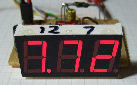
the voltmeter module, voltage is below 10 Volt
The little meter is quite versatile and relies heavily on the 10-bit ADC's in the ATMega48. Two are used here and the voltmeter module can be switched to display the voltage on channel0 or the voltage on channel1 or the voltage difference of the two channels , a low on PC4/5 turns off the channel. The idea was to measure the voltage drop across a resistor on the high side in a power supply to get the current displayed, it works but the resolution is not very good unless some amps are flowing. Displaying voltage is ok.
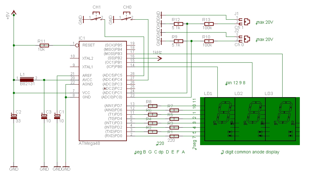
The circuit diagram.
The range is from 0 to 20 Volts but could be changed with a different resistor divider at the input. Here it is 100k / 5.1k. It needs a calibration with a reliable second voltmeter, then it can be quite accurate. In the program you'll find Const Calfactor = 2140, this need to be adjusted even if you have the same resistor values by chance, they are never exactly the same and the internal reference voltage of the ATMega48 may also vary from chip to chip. Calibration is done by measuring a voltage with the module and a second multimeter and calculate a new factor e.g. mutimeter reading / module reading * 2140 = new Calfactor. This new Calfactor is changed in the program and once compiled and programmed it's set for good. No need to adjust a trimmer, they are not very reliable anyway.
The display shows the voltage difference of channel 0 and 1 when both are connected to 5 V.
There is still a 0.02 V difference visible because the resistors are slightly different. If more accuracy is required two Calfactors could be used in the program.
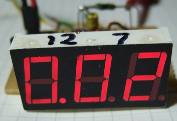
The voltmeter module is autoranging in a simple way, below 10 Volts it shows 2 digits, above the result is divided by 10 and the decimal point is moved.
the voltmeter module, voltage above 10 Volt
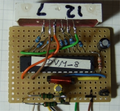
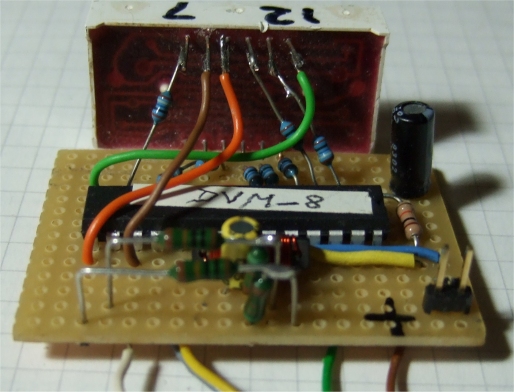
Top view, some resistors are mounted vertically to give more stability and easy connection to the display.
The segments are connected to PORTD of the ATMega48 and from there to the nearest pin of the display, the easiest way to build. It results in a somewhat unusual connection like PORTD 7-0 to seg B G C dp D E F A. No problem, software follows hardware and a lookup table in the program makes sure we can display 0 1 2 3 4 5 6 7 8 9 dp F in a correct way.
Below is the bottom view of the small board with programming wires still attached. Once the module is calibrated they are disconnected.
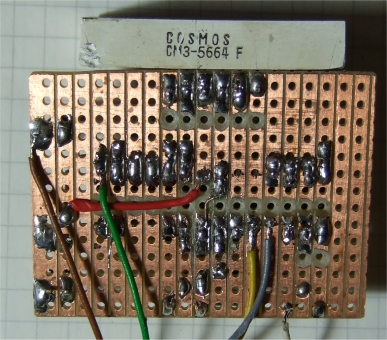
Bottom view of the board
Many things can be changed in the program to adjust the voltmeter module to
your requirements, Dispcnt changes the 100 ms refresh rate. In the interrupt
the statement Elseif Icnt = 10 Then ... can adjust the display brightness, a
higher value for Icnt will dim the display and reduce power requirements. It
needs an external 5 V power supply.und uses about 30 mA at 5V with these settings
now. The output PB5 shows which ADC channel is higher: If Adch0 > Adch1 Then...
PB5 is low. It could be connected to a led on the frontpanel.
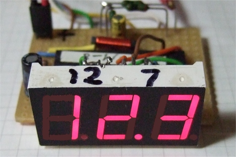
There are different ways to build the voltmeter module as you can see below. I once used this with a synchronous lock-in amplifier for a milliohm meter, but that's another story. Just to mention, that's why there still is a 1 kHz signal on PB2 and on PB4.
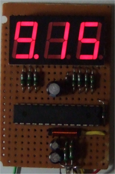
Another layout of the voltmeter module.
It' fun to build and to use.
download DVM_8.bas
This program is distributed in the hope that it will be useful but WITHOUT
ANY WARRANTY;
References
Atmel datasheet ATMega48, Atmel.com
displays with same pin assignment e. g. at https://www.lc-led.com/View/itemNumber/233
Bascom Basic Compiler
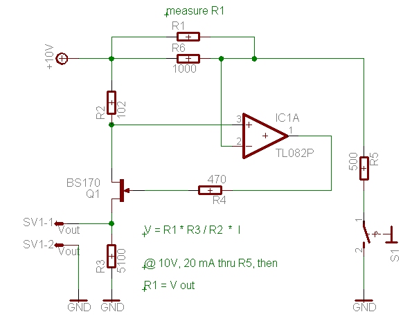
Nachtrag: Strommessung
'*********************************************************************
' ATMega 48 digital voltmeter GS 2010, display in front
' GS final 3-2011
' version for power supply voltmeter module, 0 - 20.5 V
'
' display updated in Compare1a interrupt
'
' ADC channel 0 and 1, difference displayed ch0-ch1 or ch1-ch0
' Channel0 / 1 select which channel is displayed, a low turns off channel
' 8 ADC readings each channel, Reference = Internal
' 1 kHz output 50% duty cycle on OC1B (PB2) for mOhm meter
'
' 5.1k/100k divider ADC channels
' calibrate factor: volts / ADC count
'
'***************************************************************************
'
' display 3 digits
' 7 seg digits on PORTD, segments on PORTB0,1,3
' uses 3 digit common anode 7 seg display, see below
'
' pin 12 11 10 09 08 07
' |------------------------------|
' | d1 A F d2 d3 B | |--A--|
' | | F B
' | top view | |--G--|
' | | E C
' | E D dp C G nc. | |--D--|.dp
' |------------------------------|
' pin 01 02 03 04 05 06
'
' M48 7 6 5 4 3 2 1 0 PORTD
' 7seg 7 5 4 3 2 1 10 11 pin 12 9 8 PORTB 0,1,3
' seg B G C dp D E F A dig 1 2 3 (3 = right dig)
'
'***************************************************************************
'***************************************************************************
' ATMega48 PDIP
'
' (RESET) PC6 1 28 PC5 (ADC5/SCL)
' (RXD) PD0 2 27 PC4 (ADC4/SDA)
' (TXD) PD1 3 26 PC3 (ADC3)
' (INT0) PD2 4 25 PC2 (ADC2)
' (INT1) PD3 5 24 PC1 (ADC1)
' (XCK/T0) PD4 6 23 PC0 (ADC0)
' VCC 7 22 GND
' GND 8 21 AREF
' (XTAL1/TOSC1)PB6 9 20 AVCC
' (XTAL2/TOSC2)PB7 10 19 PB5 (SCK)
' (T1) PD5 11 18 PB4 (MISO)
' (AIN0) PD6 12 17 PB3 (MOSI/OC2)
' (AIN1) PD7 13 16 PB2 (SS/OC1B)
' (ICP1) PB0 14 15 PB1 (OC1A)
'
'***************************************************************************
$regfile = "m48def.dat"
$crystal = 1000000
$hwstack = 32 ' default use 32 for the hardware stack
$swstack = 10 ' default use 10 for the SW stack
$framesize = 40 ' default use 40 for the frame space
'*********************************************************************
Showflag Alias Portb.5 'shows minus
Dpulse Alias Portb.4
Digitr Alias Portb.3
'PB2 = OC1B
Digitm Alias Portb.1
Digitl Alias Portb.0
Decpoint Alias Portd.4 'decimal point
Channel0 Alias Pinc.4 'select
Channel1 Alias Pinc.5 'a low turns off channel
'both on hi measures difference ch0-ch1 or ch1-ch0
'both on low measures nothing, ha
'*********************************************************************
Const Calfactor = 2140 'calibrate
Dim A As Byte 'the digits A B C
Dim B As Byte
Dim C As Byte
Dim I As Byte
Dim N As Byte
Dim Dp As Byte 'decimal point
Dim Flag As Byte 'status flag
Dim Dispcnt As Byte 'display counter
Dim Icnt As Byte 'ISR counter
Dim W As Word
Dim Ad As Long
Dim Adch0 As Word
Dim Adch1 As Word
Dim S(4) As String * 1
Dim Sa As String * 5
'*********************************************************************
Config Portc = Input
Portc = &B00111100
Didr0 = &B00000011 'ch1 & 2
Ddrb = &B00111111
Portb = &B00000000
Config Portd = Output
Portd = &B11111111
Ocr1b = 499 '1 kHz output
Ocr1a = 499 'for R-meter
Enable Timer1
Tccr1a = &B00010000 'CTC OC1B toggle
Tccr1b = &B00001001 'CTC, ck 1
Enable Interrupts
Enable Compare1a
On Compare1a T1cmp
Config Adc = Single , Prescaler = Auto , Reference = Internal
Start Adc
'*********************************************************************
Dp = 0
Adch0 = 0
Adch1 = 0
Flag = 0
Dispcnt = 0
W = 0
A = 0 'test display
B = 0
C = 0
Do
' measure voltage loop
If Dispcnt > 99 Then '100 ms
Dispcnt = 0 ' update display
W = 0
Adch0 = 0
If Channel0 = 1 Then
For N = 1 To 8 'get ch 0
W = Getadc(0)
Adch0 = Adch0 + W
Next N
End If
W = 0
Adch1 = 0
If Channel1 = 1 Then
For N = 1 To 8 'get ch 1
W = Getadc(1)
Adch1 = Adch1 + W
Next N
End If
If Adch0 > Adch1 Then 'show difference
Ad = Adch0 - Adch1
Showflag = 0 'show +
Else
Ad = Adch1 - Adch0
Showflag = 1 'show -
End If
Shift Ad , Right , 3 'div 8
Ad = Ad * Calfactor 'volt/count, calibrate
Ad = Ad / 1000
If Ad < 1000 Then 'move decimal point
Dp = 0
Else
Dp = 1
Ad = Ad / 10
End If
Sa = Str(ad)
Sa = Format(sa , "000")
S(1) = Mid(sa , 3 , 1)
S(2) = Mid(sa , 2 , 1)
S(3) = Mid(sa , 1 , 1)
I = Val(s(1))
A = Lookup(i , D7seg)
I = Val(s(2))
B = Lookup(i , D7seg)
I = Val(s(3))
C = Lookup(i , D7seg)
If Ad >= 205 And Dp = 1 Then 'show overflow 20.5 V
A = &B00011101
B = &B10010100
C = &B11101111
End If
If Channel0 = 0 And Channel1 = 0 Then 'surprise
A = &B11110000
B = &B01010001
C = &B10111000
End If
End If 'if dispcnt
Loop ' do again
'*********************************************************************
T1cmp: '1 ms interrupt
Toggle Dpulse
Incr Icnt
Incr Dispcnt ' update display
If Icnt = 2 Then '2 ms
Digitl = 1 ' left digit
Portd = C
If Dp = 0 Then
Decpoint = 0
End If
Elseif Icnt = 4 Then
Decpoint = 1
Digitl = 0
Digitm = 1 ' middle digit
Portd = B
If Dp = 1 Then
Decpoint = 0 ' dp
End If
Elseif Icnt = 6 Then
Decpoint = 1
Digitm = 0
Digitr = 1 ' right digit
Portd = A
Elseif Icnt = 8 Then 'adjust brightness
Digitr = 0
Portd = 0
Elseif Icnt = 10 Then
Icnt = 0
End If
Return 'reti
End
'*********************************************************************
' 0 1 2 3 4 5 6 7 8 9 dp F
D7seg:
Data &B01010000 , &B01011111 , &B00110010 , &B00010110 , &B00011101 , &B10010100 , &B10010001 , &B01011110 , &B00010000 , &B00011100 , &B11101111 , &B10111000
'*********************************************************************
' Connections of the seven segment elements:
' dec hex
' 0| - f a b c d e | 01010000 | 50
' 1| - - - b c - - | 01011111 | 5f
' 2| g - a b - d e | 00110010 | 32
' 3| g - a b c d - | 00010110 | 16
' 4| g f - b c - - | 00011101 | 1d
' 5| g f a - c d - | 10010100 | 94
' 6| g f a - c d e | 10010001 | 91
' 7| - - a b c - - | 01011110 | 5e
' 8| g f a b c d e | 00010000 | 10
' 9| g f a b c d - | 00011100 | 1c
' digit to seven segment LED mapping:
' seg B G C dp D E F A